
Circuit Arrangement for Operation of at Least One LED

a technology of circuit arrangement and led, which is applied in the direction of electroluminescent light source, electric lighting source, and use of semiconductor lamps, etc., can solve the problems of comparatively complex circuit and high cos

Inactive Publication Date: 2012-07-12
OSRAM GMBH
View PDF4 Cites 3 Cited by
  • Summary
  • Abstract
  • Description
  • Claims
  • Application Information

AI Technical Summary

Benefits of technology

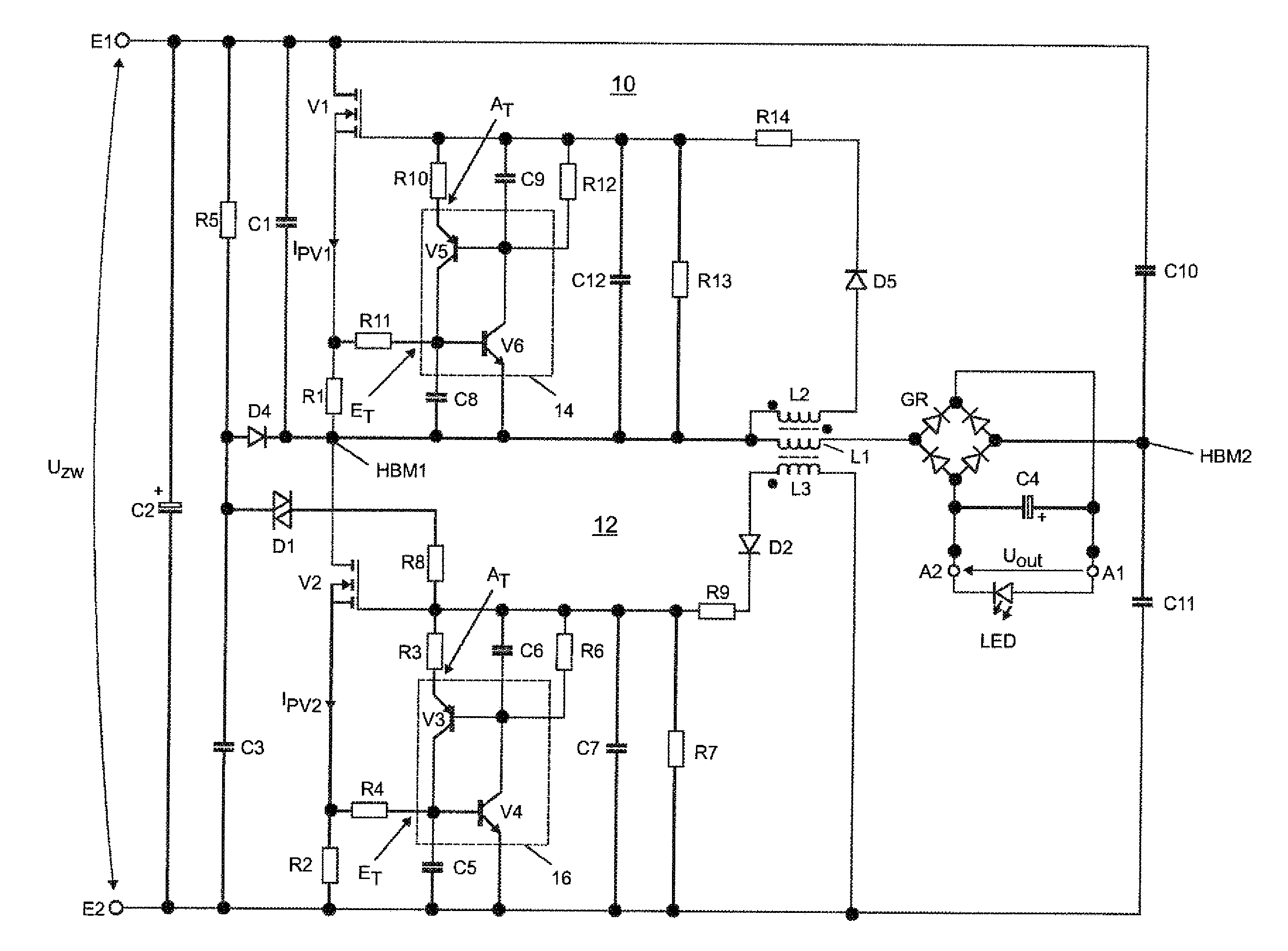
[0005]The present invention is based on the knowledge that said object can be achieved in a particularly simple manner if the circuit arrangement is conceived as a free oscillator. To that extent the drive circuit includes a first and a second control device, wherein the first control device includes a second inductor which is magnetically coupled to the first inductor, and wherein the second control device includes a third inductor which is magnetically coupled to the first inductor. By means of said measures the need for an integrated circuit is removed. As a result thereof the requirements that applied in the prior art in order to derive a supply voltage for the integrated circuit from the rectified line voltage can be dispense with. The circuit is furthermore characterized by a high level of efficiency as well as by a symmetric magnetic modulation of the first inductor.
[0015]A rectifier is preferably coupled between the first inductor and the output of the circuit arrangement. This then ensures that the LED is provided with a direct current. The LED can, however, also be coupled via a separate transformer whose primary winding is coupled in series with the first inductor and to the secondary winding of which the rectifier is connected, without altering the principle of operation of the circuit. Potential freedom for the LED can be established in this way.

Problems solved by technology

The circuit is comparatively complex and expensive as a result.

Method used


Image

  • Circuit Arrangement for Operation of at Least One LED
  • Circuit Arrangement for Operation of at Least One LED
  • Circuit Arrangement for Operation of at Least One LED

Examples


Embodiment Construction

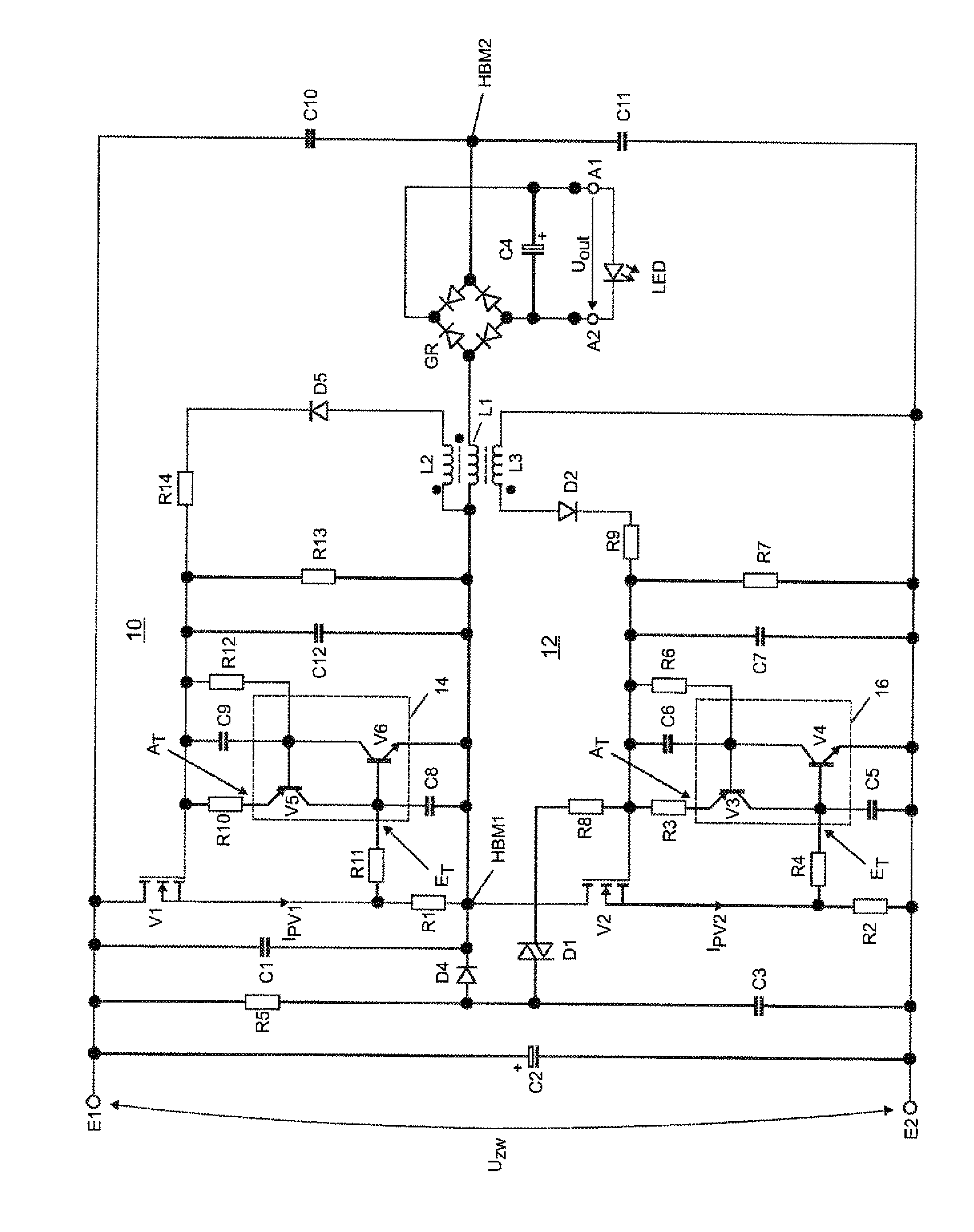
[0019]The single FIGURE shows an exemplary embodiment of a circuit arrangement according to the invention in a schematic representation. A supply voltage UZw, which can represent in particular what is termed the direct-current link voltage, is connected to an input with a first and a second input terminal. A capacitor C2 is provided for the purpose of stabilizing said voltage. The alternating component of the voltage UZw present at the input can be influenced by the dimensioning of the capacitor C2. The ratio of alternating component to direct component of the voltage UZw affects the radio frequency interference caused by the circuit arrangement.

[0020]The circuit includes an inverter having two transistors V1, V2 in a half-bridge arrangement. Connected to the transistor V1, V2 is a source resistor R1, R2, respectively, which serves for measuring the current through the respective transistor V1, V2. A first half-bridge center point HBM1 of the circuit arrangement is formed between V1...


PUM


Abstract

In various embodiments, a circuit for operating an LED includes input terminals for coupling to a supply voltage; output terminals for providing output DC voltage(s) to the LED(s); an inverter having a bridge circuit with at least first and second electronic switches comprising control electrodes, reference electrodes and working electrodes, wherein first and second electronic switches are serially coupled between input terminals, forming a first bridge center point; a first inductor serially coupled between first bridge center point and an output terminal; and a drive circuit having output terminals, wherein one output terminal is coupled to control electrode of first electronic switch and second output terminal is coupled to control electrode of second electronic switch; configured so that-drive circuit comprises control devices, wherein one control device includes a second inductor magnetically coupled to the first inductor, and wherein second control device includes third inductor magnetically coupled to first inductor.

Description

TECHNICAL FIELD[0001]The present invention relates to a circuit arrangement for operating at least one LED, said circuit arrangement having an input with a first and a second input terminal for coupling to a supply voltage, an output with a first and a second output terminal for providing an output DC voltage to the at least one LED, an inverter having a bridge circuit with at least one first and one second electronic switch, wherein the first and the second electronic switch each include a control electrode, a reference electrode and a working electrode, wherein the first and the second electronic switch are serially coupled between the first and the second input terminal, forming a first bridge center point, a first inductor which is serially coupled between the first bridge center point and one of the output terminals, and a drive circuit having at least one first and one second output terminal, wherein the first output terminal is coupled to the control electrode of the first el...

Claims


Application Information

Patent Timeline
Patent Type & Authority Applications(United States)
IPC IPC(8): H05B37/00H05B44/00
CPCH05B33/0815Y02B20/348Y02B20/346Y02B20/30H05B45/39
Inventor RUDOLPH, BERND
Owner OSRAM GMBH
Learn More