Indirect additive manufacturing process for fabricating bonded soft magnets

a manufacturing process and soft magnet technology, applied in the direction of additive manufacturing with solid and fluid, magnetic materials, magnetic bodies, etc., can solve the problems of high manufacturing cost, limited productivity, and steel becoming too brittle to be cold rolled or stamped without cracking, etc., to achieve cost-effective

Pending Publication Date: 2021-02-25
UT BATTELLE LLC +1
View PDF3 Cites 3 Cited by
  • Summary
  • Abstract
  • Description
  • Claims
  • Application Information

AI Technical Summary

Benefits of technology

[0006]The present disclosure is foremost directed to indirect additive manufacturing (IAM) methods for producing objects constructed of bonded soft magnet particles composed of an iron-containing alloy having a soft magnet characteristic. The soft magnet particles and resulting bonded object may have, for example, an iron-silicon, iron-cobalt, iron-nickel, iron-cobalt-silicon, or iron-nickel-silicon composition. In contrast to the conventional art, the present method advantageously produces objects composed of a soft magnet material of any structural complexity and without the cracks and other defects commonly found in such objects produced according to the conventional art. The present method is particularly advantageous in its capability of producing such complex and defect-free objects even when the object has a high silicon content, such as a silicon content of at least or above 3, 4, 5, or 6 wt. %. The method is further advantageous in that it is relatively straight-forward and can produce soft magnet objects of highly complex shapes in a very cost-effective manner.

Problems solved by technology

% Si), the steel becomes too brittle to be cold rolled or stamped without cracking, particularly during production of thin sheets.
However, the manufacturing cost is high, productivity is limited, and the final product is brittle and difficult to stamp.
% Si can be hot- and cold-rolled as well as stamped with texture, but these processing methods generally require many heat treatments to achieve adequate magnetic properties and cannot be performed with increased Si content due to brittleness.

Method used


Image

  • Indirect additive manufacturing process for fabricating bonded soft magnets
  • Indirect additive manufacturing process for fabricating bonded soft magnets
  • Indirect additive manufacturing process for fabricating bonded soft magnets

Examples


examples

[0050]Overview

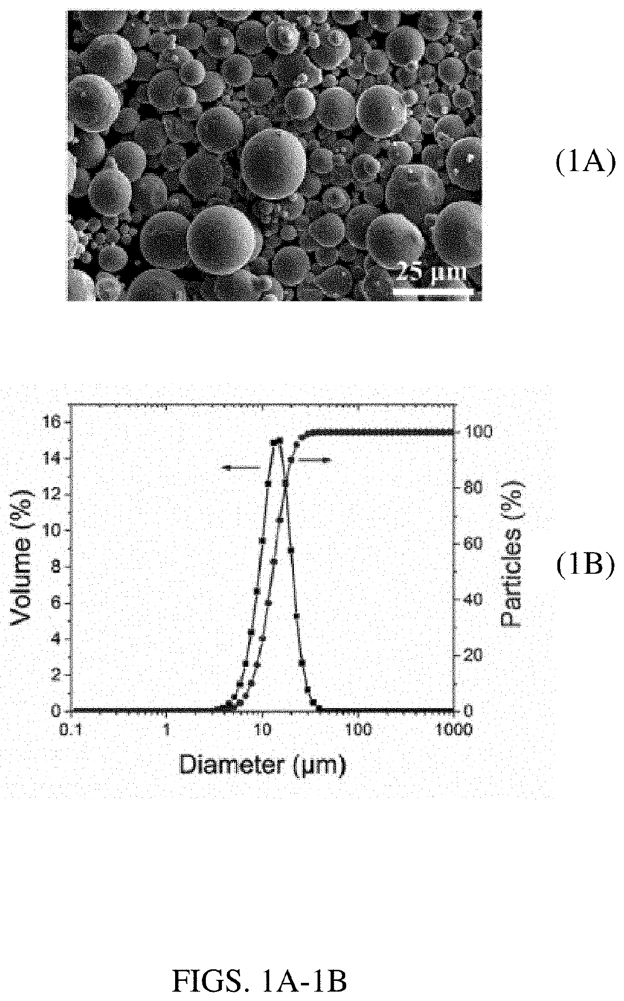
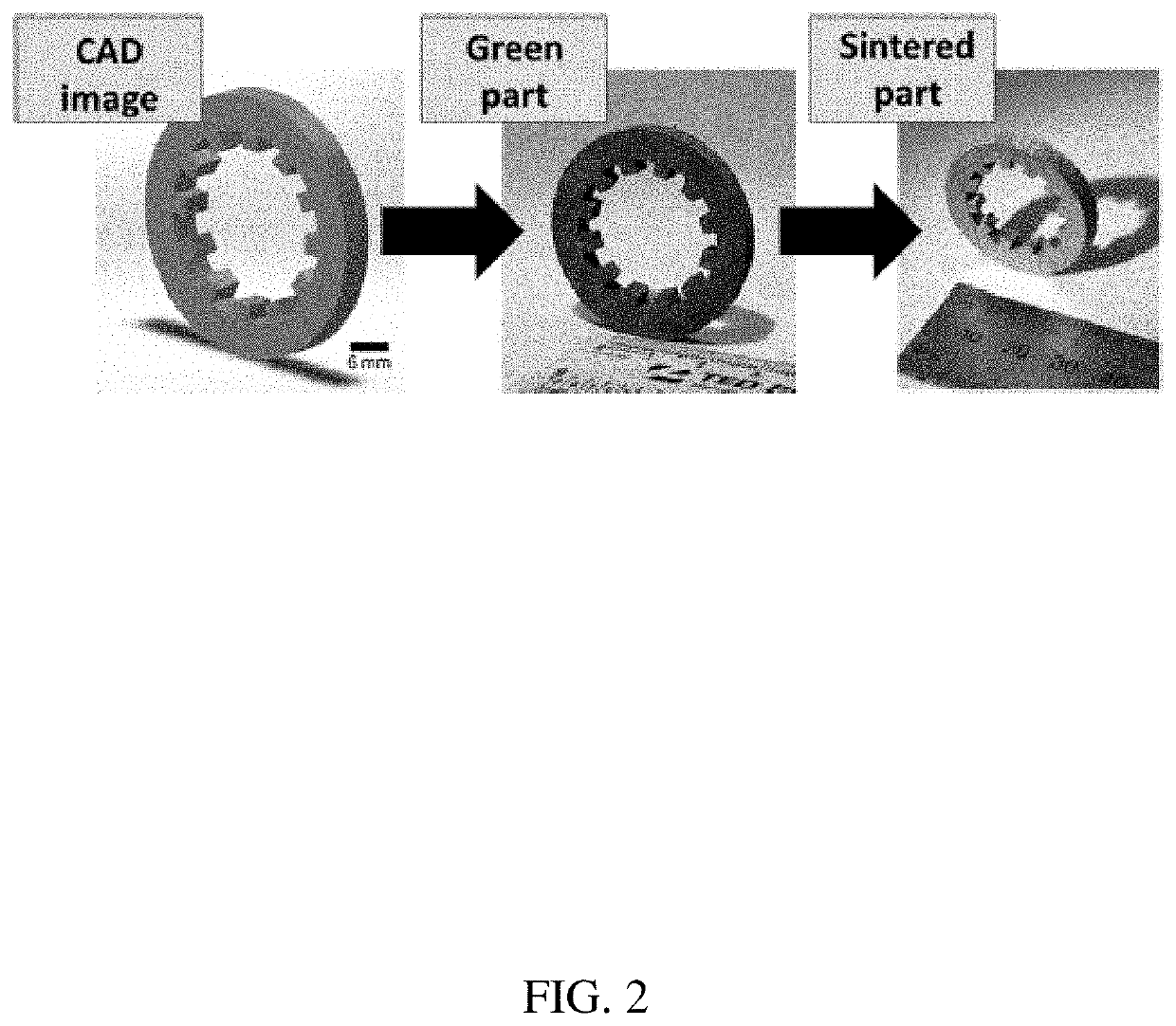
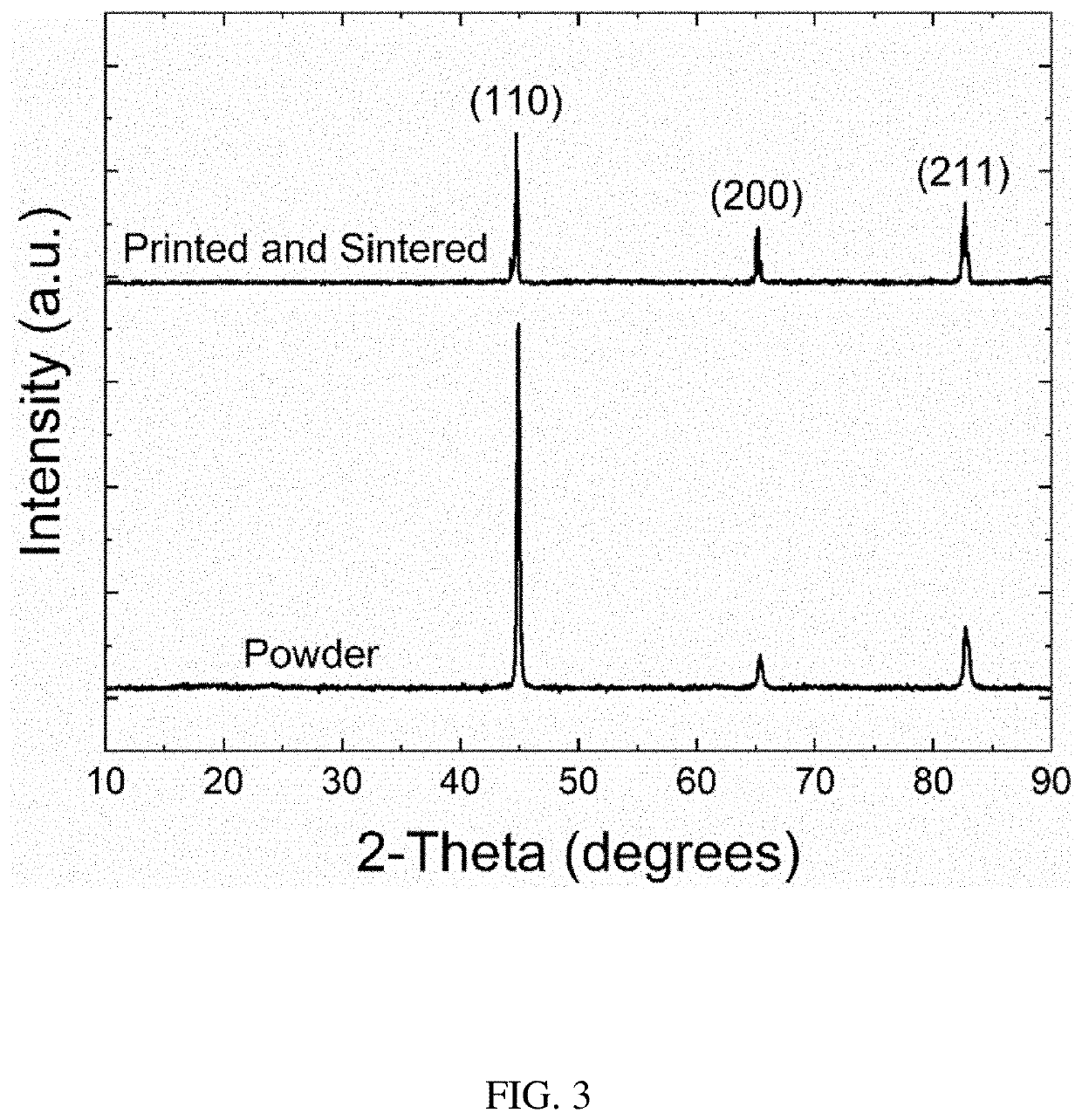
[0051]In the present work, Fe with 6.5 wt. % Si (i.e., “Fe-6.5 Si”) soft magnetic material was printed using a BJAM process. Parts were cured, followed by debinding, and solid-state sintered to high densities without cracking. The parts had excellent magnetic (both direct current (DC) and alternating current (AC) core loss properties) and mechanical properties. The microstructure was revealed with scanning electron microscopy (SEM) and electron backscatter diffraction (EBSD) showing grain size, orientation, and texture of solid-state sintered samples. In contrast to the conventional art, the presently described bonded material successively achieved additively printed Fe-6 Si or Fe-6.5 Si components without cracking. The BJAM-processed 6.5% silicon steel parts with outstanding soft magnetic properties (high magnetic induction, high permeability, and low coercivity), along with defect-free nature, represent a significant advance in the power electronics industry.

[0052]Bu...


PUM

PropertyMeasurementUnit
particle sizeaaaaaaaaaa
sizeaaaaaaaaaa
sizeaaaaaaaaaa

Abstract

A bonded soft magnet object comprising bonded soft magnetic particles of an iron-containing alloy having a soft magnet characteristic, wherein the bonded soft magnetic particles have a particle size of at least 200 nm and up to 100 microns. Also described herein is a method for producing the bonded soft magnet by indirect additive manufacturing (IAM), such as by: (i) producing a soft magnet preform by bonding soft magnetic particles with an organic binder, wherein the magnetic particles have an iron-containing alloy composition with a soft magnet characteristic, and wherein the particles of the soft magnet material have a particle size of at least 200 nm and up to 100 microns; (ii) subjecting the preform to an elevated temperature sufficient to remove the organic binder to produce a binder-free preform; and (iii) sintering the binder-free preform at a further elevated temperature to produce the bonded soft magnet.

Description

CROSS REFERENCE TO RELATED APPLICATION[0001]The present application claims benefit of U.S. Provisional Application No. 62 / 889,606, filed on Aug. 21, 2019, all of the contents of which are incorporated herein by reference.GOVERNMENT SUPPORT[0002]This invention was made with government support under Prime Contract No. DE-AC05-00OR22725 awarded by the U.S. Department of Energy. The government has certain rights in the invention.FIELD OF THE INVENTION[0003]The present invention relates generally to soft magnet compositions, particularly iron-containing magnetic alloys. The present invention also relates to methods of additive manufacturing of metals and alloy materials.BACKGROUND OF THE INVENTION[0004]Soft magnetic silicon steel with 3 wt. % Si is widely used in electrical applications such as transformers, magnetic shielding, motor stators, and generators in applications where high permeability and low losses are required. Increasing Si content improves magnetic and electrical properti...

Claims


Application Information

Patent Timeline
Patent Type & Authority Applications(United States)
IPC IPC(8): H01F41/02H01F1/147H01F1/33C22C38/02B29C64/165B22F3/00B22F1/00B33Y10/00B33Y70/10B22F1/052B22F1/102
CPCH01F41/02H01F1/14775H01F1/33C22C38/02B29C64/165B22F2304/058B22F1/0062B33Y10/00B33Y70/10B22F2304/10B22F2304/056B22F3/008B33Y40/20B29C64/30B33Y80/00H01F3/08H01F41/0246B22F10/14C22C33/0228C22C33/0278C22C32/0094C22C32/0026B22F2998/10B22F2999/00Y02P10/25B22F1/052B22F1/102B22F3/1021B22F3/10B22F2003/248C22C2202/02B22F10/00H01F1/22
Inventor PARANTHAMAN, MARIAPPAN PARANSCRAMER, CORSON L.NANDWANA, PEEYUSHELLIOTT, AMELIA M.CHINNASAMY, CHINS
Owner UT BATTELLE LLC
Why Eureka
Try Eureka