Fuel injection control device and fuel injection control method for internal combustion engine

a control device and control method technology, applied in the direction of electric control, machines/engines, output power, etc., can solve the problems of increasing the likelihood of knocking and the inability to achieve the torque that should be obtained through achieving a high compression ratio, and achieve the effect of reliable suppression of knocking

Inactive Publication Date: 2017-02-02
NISSAN MOTOR CO LTD
View PDF19 Cites 4 Cited by
  • Summary
  • Abstract
  • Description
  • Claims
  • Application Information

AI Technical Summary

Benefits of technology

[0006]The compression stroke is a compression in a state in which the intake valve and the exhaust valve are closed, which can be considered as an adiabatic compression stroke. If fuel is injected in the course of such an adiabatic compression stroke, while a decrease in the gas temperature inside the cylinder due to evaporative latent heat does occur, the effect of reducing the gas temperature inside the cylinder near the top dead center in which knocking is likely to occur is small. In other words, there is room for improvement in the control of the above-described document, as a control for suppressing knocking.
[0007]Therefore, the object of the present invention is to carry out a fuel injection control that is capable of more reliably suppressing knocking.

Problems solved by technology

However, in an internal combustion engine that uses gasoline as fuel, knocking becomes more likely to occur as the compression ratio is increased and, thus, it becomes necessary to take measures to suppress the knocking.
That is, by retarding the ignition timing, the torque that should be obtainable through achieving a high compression ratio cannot be obtained.

Method used


Image

  • Fuel injection control device and fuel injection control method for internal combustion engine
  • Fuel injection control device and fuel injection control method for internal combustion engine
  • Fuel injection control device and fuel injection control method for internal combustion engine

Examples


Embodiment Construction

[0019]Embodiments of the present invention will be described below, with reference to the appended drawings.

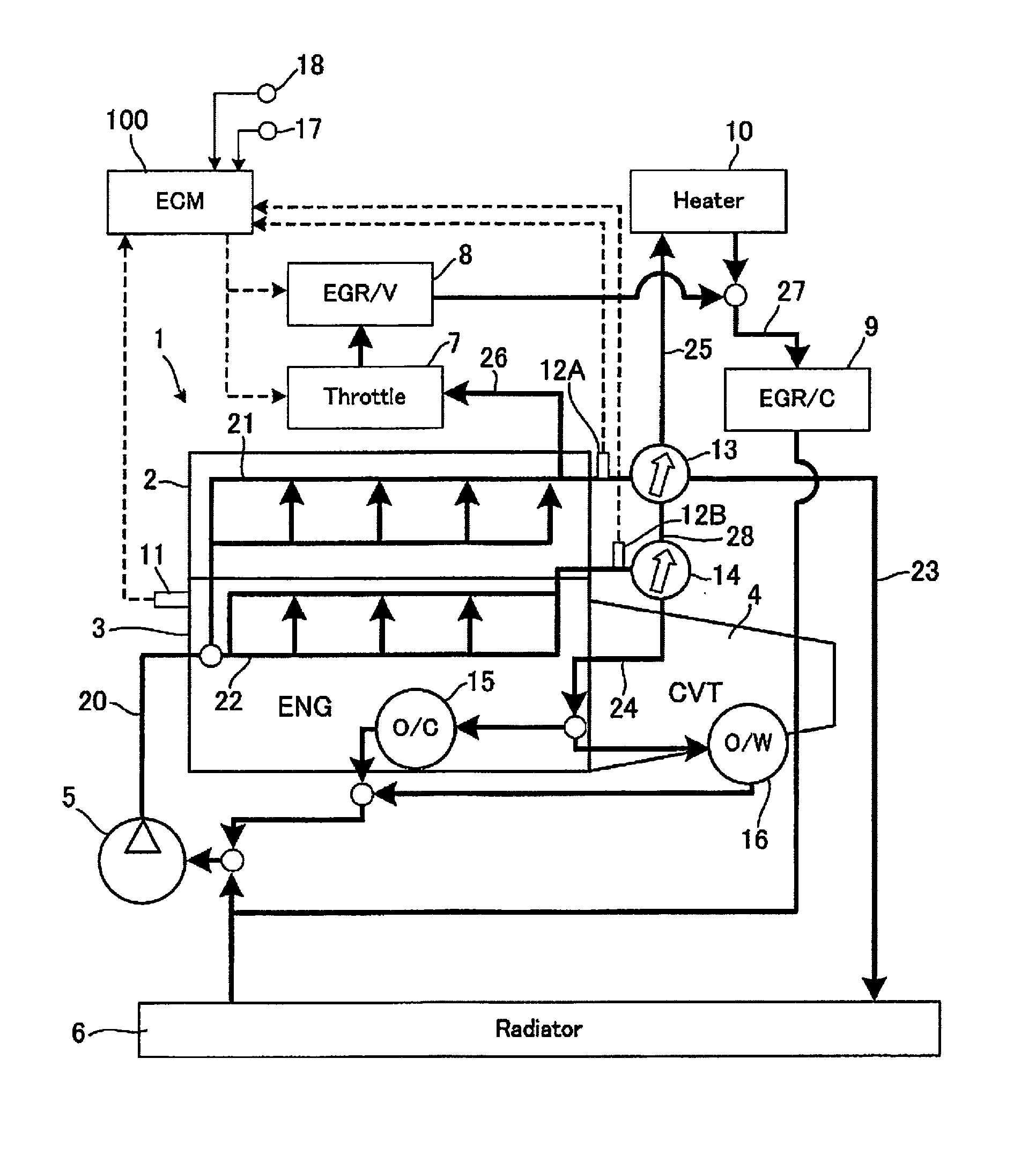
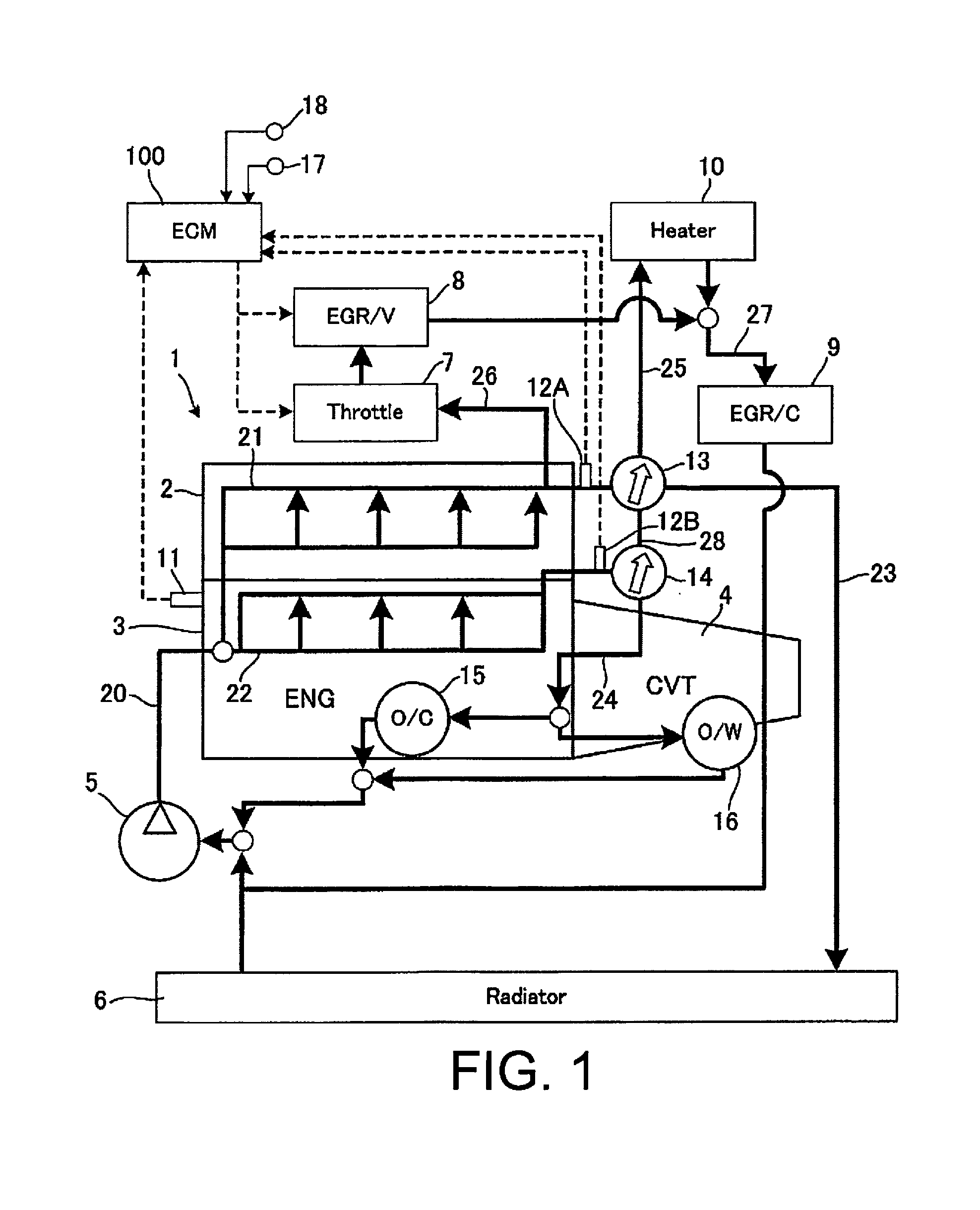
[0020]FIG. 1 is a block diagram illustrating one example of a cooling system to which is applied the present embodiment. The present cooling system cools an internal combustion engine 1 by circulating cooling water using a water pump 5 that is driven by a spark-ignition internal combustion engine having direct fuel injection into a cylinder (hereinafter also simply referred to as “internal combustion engine”) 1. The water pump 5 may be an electric pump that is driven by an electric motor as well.

[0021]The cooling water channel inside the internal combustion engine 1 is branched into two lines, a head-side cooling channel 21 provided in a cylinder head 2, and a block-side cooling channel 22 provided in a cylinder block 3. A first control valve 13 is disposed on the cylinder head outlet side of the head-side cooling channel 21, and a second control valve 14 is provided on the cy...


PUM


Abstract

A fuel injection control device controls fuel injection of a spark-ignition internal combustion engine for direct injection into a cylinder and independently controls circulation of a coolant in a head-side cooling channel and in a block-side cooling channel. The fuel injection control device is provided with a controller that sets a fuel injection timing for cooling the inside of the cylinder such that an intake valve closing timing occurs during a reduction in gas temperature inside the cylinder due to evaporative latent heat of the injected fuel, while the coolant circulates in the head-side cooling channel and the circulation of the coolant in the block-side cooling channel is stopped. The controller injects the fuel based on the fuel injection timing for cooling the inside of the cylinder.

Description

CROSS-REFERENCE TO RELATED APPLICATIONS[0001]This application is a U.S. National stage application of International Application No. PCT / JP2014 / 063002, filed May 15, 2014.BACKGROUNDField of the Invention[0002]The present invention relates to a fuel injection control device and a fuel injection control method for an internal combustion engine.[0003]Background Information[0004]Increasing the compression ratio is an effective measure to improve the thermal efficiency of an internal combustion engine to improve the fuel efficiency. However, in an internal combustion engine that uses gasoline as fuel, knocking becomes more likely to occur as the compression ratio is increased and, thus, it becomes necessary to take measures to suppress the knocking. For example, retarding the ignition timing is a known method to suppress knocking, but the torque is reduced as the ignition timing is retarded. That is, by retarding the ignition timing, the torque that should be obtainable through achieving ...

Claims


Application Information

Patent Timeline
Patent Type & Authority Applications(United States)
IPC IPC(8): F02D41/30F02D41/26
CPCF02D41/3005F02D2200/021F02D2250/14F02D41/263F02D41/22F02D41/047F02D41/345F02D41/402F02D13/0234Y02T10/40F02D41/34F01P2003/027F01P7/165F01P3/02F01P7/16
Inventor IMAOKA, YOSHIHIROINOUE, TAKAO
Owner NISSAN MOTOR CO LTD
Why Eureka
Try Eureka