

Polarized light source device
- Summary
- Abstract
- Description
- Claims
- Application Information
AI Technical Summary
Benefits of technology
Problems solved by technology
Method used
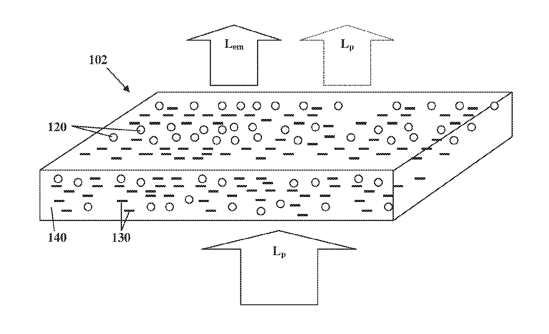
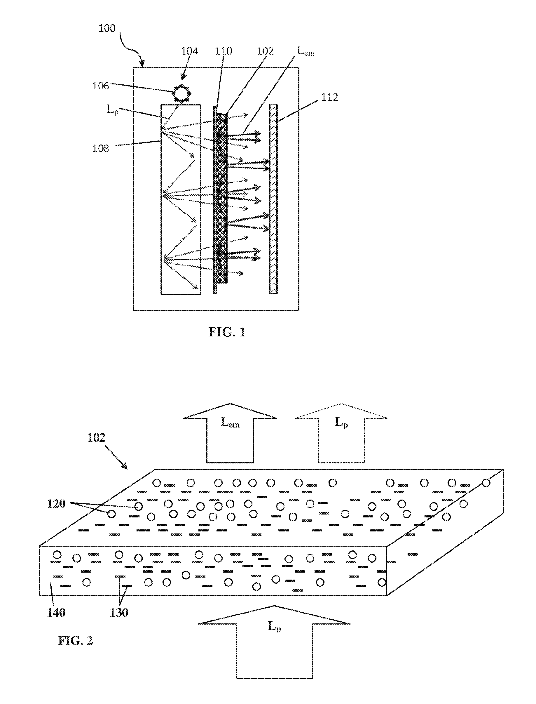
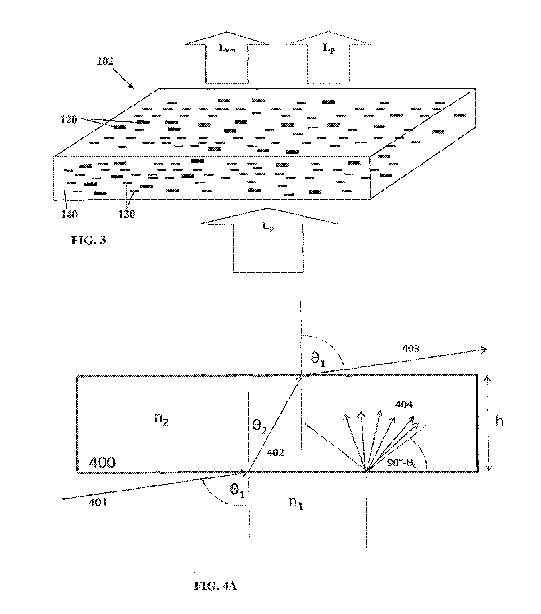
Image

Examples
example 1
[0130]In order to construct a backlight unit, aligned nanorods film was placed on the surface of a lightguide plate (slab) coupled to a pumping light source in the form of a blue emitting LED bar (central wavelength 450 nm FWHM=20 nm, edge-lit). A highly reflective sheet based on Silver layer coating was placed in the back surface of the lightguide in order to recycle the light emitted backwards.
[0131]The polarized light output from the nanorods layer was directed to pass through a polarization maintaining diffuser (in this non-limiting example LSD™ holographic diffuser, circular 30 degrees, available from Luminit was used) to improve brightness uniformity.
[0132]As a light redirecting film, a Reflexite collimating film (RCF™) commercially available from Orafol Europe GmbH was used. A specific batch had the desired birefringence alignment axes that are along the facet of the light redirecting films' prism. This film was placed parallel to the nanorods alignment axis or in a perpendic...
example 2
[0134]In order to construct a backlight unit, the aligned nanorods film was placed on the surface of a lightguide plate (slab) coupled to a blue emitting LED bar (central wavelength 450 nm FWHM=20 nm, edge-lit). A highly reflective sheet based on Silver layer coating (“BL film”, commercially available from Oike) was placed in the back surface of the lightguide in order to recycle the light emitted backwards.
[0135]As a light redirecting film, a prism film with 160 um pitch and prisms with angle 90 degrees was used. A specific film with a non-birefringent polymethyl-methacrylate (PMMA) substrate was chosen (250 micron substrate with retardation below 25 nm). This film was placed parallel to the nanorods alignment axis or in a perpendicular alignment. In both alignments, the polarization ratio received was 2. The LROE film provided an increase of 60-80% for the green and red light compared to 10-40% increase obtained using prism films which are based on birefringent polymer substrates....
PUM
 Abstract
Description
Claims
Application Information