Spark plug

a technology of spark plugs and plugs, applied in spark plugs, basic electric elements, electric devices, etc., can solve the problems of reducing affecting so as to improve the life of spark plugs. the effect of the lifetim

Active Publication Date: 2017-02-02
NGK SPARK PLUG CO LTD
View PDF4 Cites 9 Cited by
  • Summary
  • Abstract
  • Description
  • Claims
  • Application Information

AI Technical Summary

Benefits of technology

[0022]It is possible in this configuration to improve the lifetime of the spark plug in which the electrode tip is joined to at least one of the center electrode and the ground electrode.

Problems solved by technology

It is thus likely that a crack (fracture) and an oxide scale will occur at boundaries between the electrode tip and the fused part and between the electrode base and the fused part.
In the case where at least one of a crack and an oxide scale is developed excessively at such boundaries, the electrode tip may become separated and fall off from the electrode base.

Method used


Image

  • Spark plug
  • Spark plug
  • Spark plug

Examples


first embodiment

A. First Embodiment

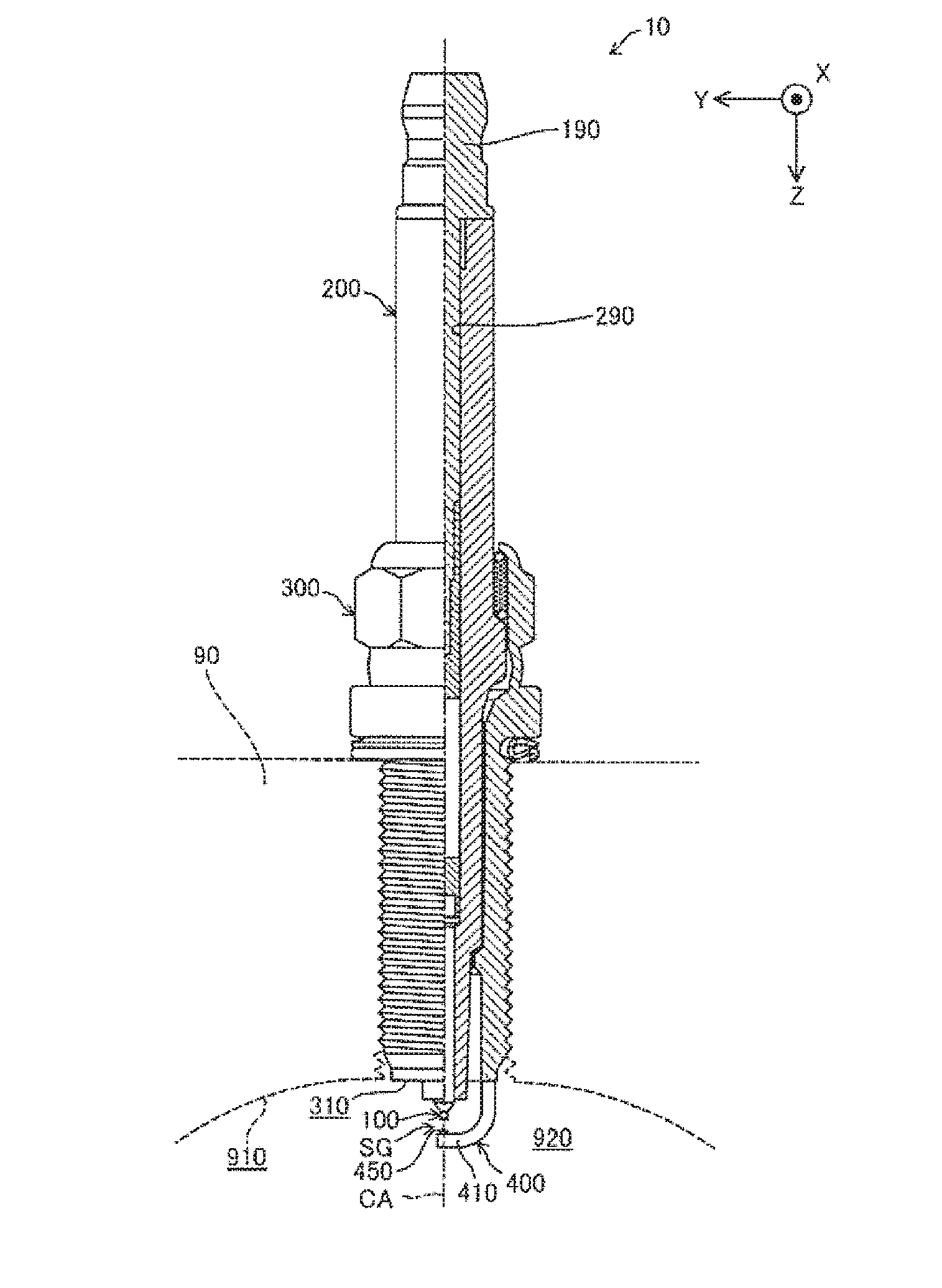
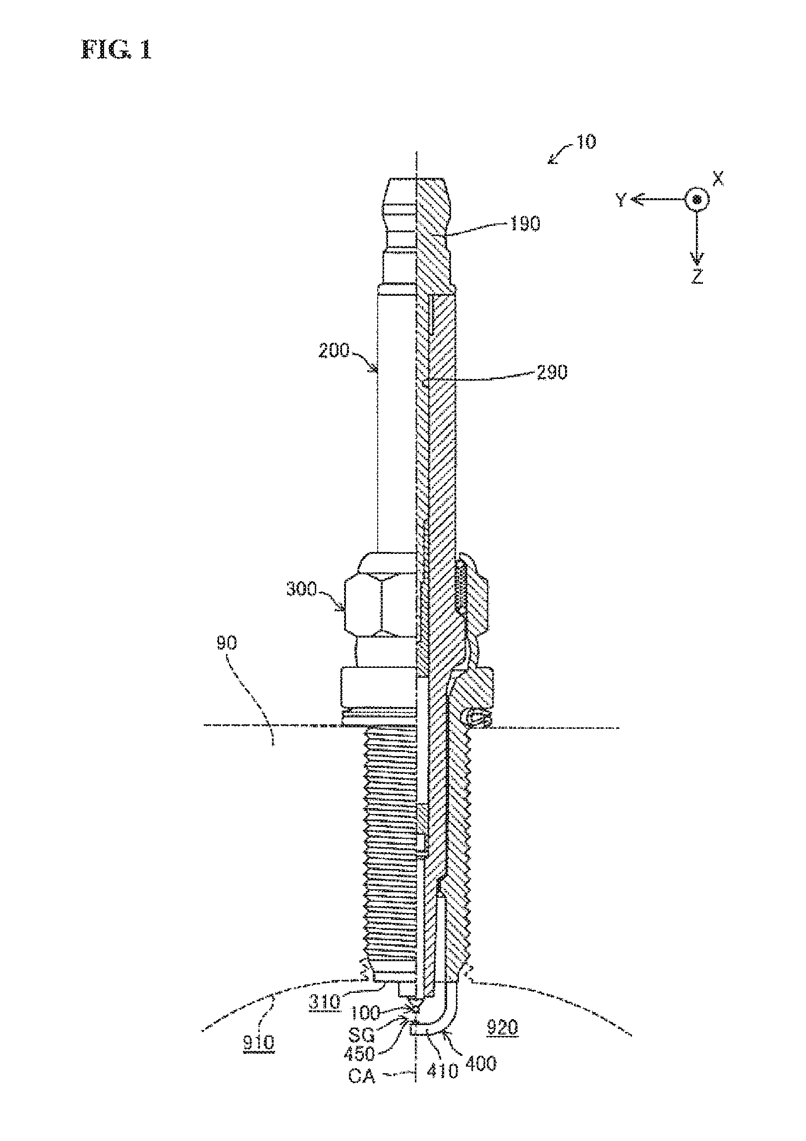
[0040]FIG. 1 is a schematic view, partially in section, of a spark plug 10 according a first embodiment of the present invention. In FIG. 1, an axis of the spark plug 10 is designated by CA. The left side of the axis CA in FIG. 1 shows an appearance of the spark plug 10, whereas the right side of the axis CA in FIG. 1 shows a cross section of the spark plug 10. In the following description, the bottom and top sides of FIG. 1 are referred to as front and rear sides of the spark plug 10, respectively.

[0041]The spark plug 10 includes a center electrode 100, an insulator 200, a metal shell 300 and a ground electrode 400. In the first embodiment, the axis CA of the spark plug 10 is in agreement with axes of the center electrode 100, the insulator 200 and the metal shell 300.

[0042]In a front end side of the spark plug 10, there is a gap SG defined between the center electrode 100 and the ground electrode 400. The gap SG of the spark plug 10 is called a spark gap. The sp...

second embodiment

B. Second Embodiment

[0098]FIG. 5 is a cross-sectional view of a distal end part of a ground electrode 401 of a spark plug according to a second embodiment of the present invention. The spark plug 10 of the second embodiment is the same as that of the first embodiment, except that the ground electrode 401 of the second embodiment is different from the ground electrode 400 of the first embodiment. More specifically, the ground electrode 401 of the second embodiment is the same as the ground electrode 400 of the first embodiment, except that the ground electrode 401 has a clearance between the recess 418 of the electrode base and the tip surface 454 of the electrode tip 450. It is possible in the second embodiment to improve the lifetime of the spark plug 10 in the same manner as in the first embodiment.

third embodiment

C. Third Embodiment

[0099]FIG. 6 is a cross-sectional view of a distal end part of a ground electrode 402 of a spark plug according to a third embodiment of the present invention. The spark plug 10 of the third embodiment is the same as that of the first embodiment, except that the ground electrode 402 of the third embodiment is different from the ground electrode 400 of the first embodiment. More specifically, the ground electrode 402 of the third embodiment is the same as the ground electrode 400 of the first embodiment, except that the tip surface 453 of the electrode tip 450 is flush with the base surface 413 of the electrode base 410 in the ground electrode 402. It is possible in the third embodiment to improve the lifetime of the spark plug 10 in the same manner as in the first embodiment.


PUM


Abstract

Disclosed is a spark plug with improved lifetime. The spark plug includes a first electrode and a second electrode having an electrode base and an electrode tip joined to the electrode base with a gap defined between the first electrode and the electrode tip. The electrode tip has a flat surface located apart from the electrode base and is joined to the electrode base at a side opposite to the flat surface by laser welding with emission of laser beam in a plane direction from one to the other end of the flat surface. A fused part is formed by the laser welding at the opposite side of the electrode tip. A cross-sectional shape of the fused part taken along a plane perpendicular to the flat surface and parallel to the plane direction has a constricted section at a position from one side to the other side in the plane direction.

Description

FIELD OF THE INVENTION[0001]The present invention relates to a spark plug.BACKGROUND OF THE INVENTION[0002]A spark plug is known, in which an electrode tip is joined to an electrode base for improvement in electrode durability (see, for example, Japanese Laid-Open Patent Publication No. 2010-238498). In this type of spark plug, the electrode tip is formed of a material having higher spark resistance and oxidation resistance to those of the electrode base. As such an electrode tip material, a noble metal (e.g. platinum, iridium, ruthenium or rhodium) or a material containing a noble metal can be used as a main component.[0003]The spark plug of Japanese Laid-Open Patent Publication No. 2010-238498 includes a fused part formed by laser welding between the electrode tip and the electrode base such that the fused part has a tapered shape (so called “wedge shape”) in the emission direction of a laser beam during the laser welding.[0004]When the spark plug is used in an internal combustion...

Claims


Application Information

Patent Timeline
Patent Type & Authority Applications(United States)
IPC IPC(8): H01T13/39
CPCH01T13/39H01T13/32
Inventor SUZUKI, KAORI
Owner NGK SPARK PLUG CO LTD
Why Eureka
Try Eureka