
High Efficiency Uninterruptible Power Supply with Near Loss-Less Ultrafast Electromechanical Switching

a high-efficiency, ultra-fast technology, applied in the direction of emergency power supply arrangements, contact mechanisms, generators/motors, etc., can solve the problems of limiting the amount of ups power consumption that can be reduced, power disruption could have very serious adverse consequences, etc., and achieve the effect of reducing power losses

Active Publication Date: 2017-02-02
POWERPATH TECH INC
View PDF5 Cites 8 Cited by
  • Summary
  • Abstract
  • Description
  • Claims
  • Application Information

AI Technical Summary

Benefits of technology

The present invention provides a UPS system that overcomes the disadvantages of conventional UPS systems by using mechanical switches driven by an electromechanical actuator, resulting in reduced power losses and improved performance characteristics during fault conditions. The UPS system can be programmed to operate in different modes and is reconfigurable or re-programmable. The speed of the electromechanical actuator powered mechanical switch of the present invention is faster than that of conventional UPS systems, making it more efficient. Overall, the present invention provides a more efficient, reliable, and flexible UPS system for improved performance and reliability.

Problems solved by technology

A UPS system is typically used to protect hardware, such as computers, data centers, telecommunications equipment, medical equipment, and other types of mission critical electrical equipment, where an unexpected power disruption could have very serious adverse consequences.
Unfortunately, there is a limit to how much UPS power consumption can be reduced because they use semiconductor power switching arrangements, typically SCR switches, which must remain powered during UPS operation.

Method used


Image

  • High Efficiency Uninterruptible Power Supply with Near Loss-Less Ultrafast Electromechanical Switching
  • High Efficiency Uninterruptible Power Supply with Near Loss-Less Ultrafast Electromechanical Switching
  • High Efficiency Uninterruptible Power Supply with Near Loss-Less Ultrafast Electromechanical Switching

Examples


Embodiment Construction

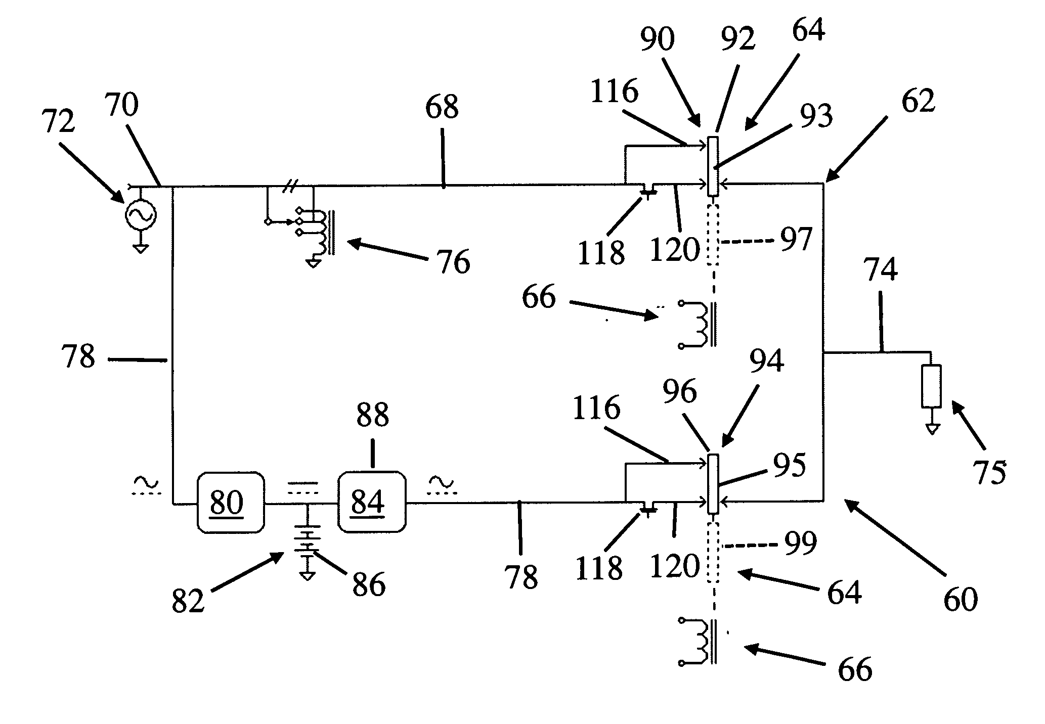
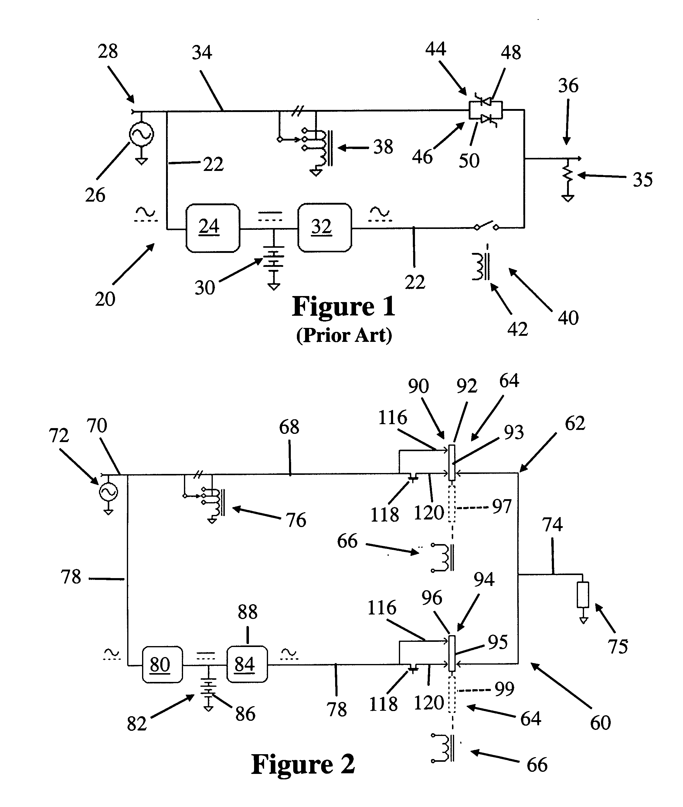
[0022]The present invention is directed to an uninterruptible power supply, uninterruptible power source, or UPS system, having improved performance and providing increased efficiency over conventional UPS systems presently in use. Before discussing the present invention in considerable detail hereinbelow with regard to FIGS. 2-7B, a brief introduction to conventional UPS systems is discussed immediately below with reference to FIG. 1.

Introduction

[0023]FIG. 1 schematically illustrates a generic example of a conventional UPS system 20 that is presented together with the accompanying discussion below in order to not only provide a helpful general introduction to UPS systems, but also to set the stage for highlighting the novelty, differences, unique features, and advantages of a UPS system constructed in accordance with the present invention discussed in even more detail further below. Existing UPS systems are divided into three general classes: on-line, off-line, and line-interactive...


PUM


Abstract

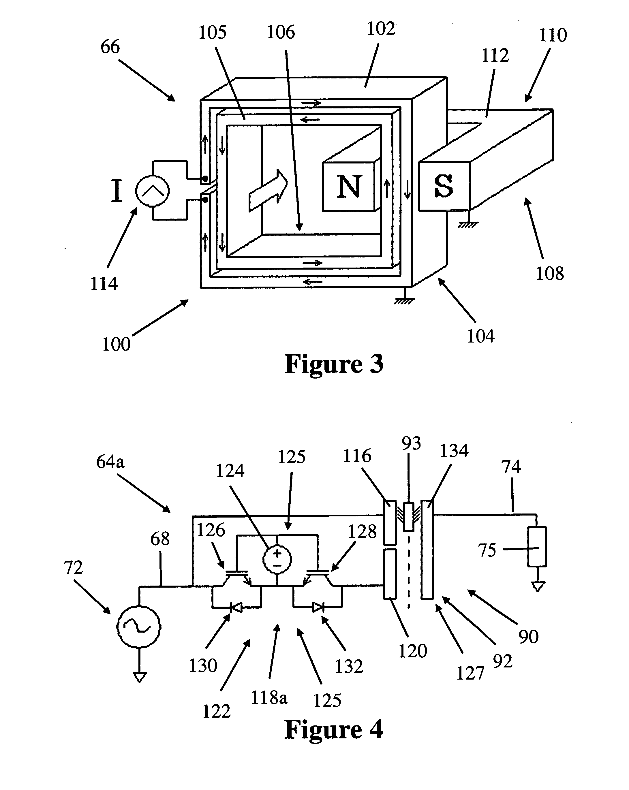
A UPS system and mechanical switching arrangement therefor that is driven by an electromechanical actuator when a fault condition is detected thereby opening or closing a switch of the switching arrangement in response thereto within 8 milliseconds, preferably within 4 milliseconds, and more preferably within 2 milliseconds of a fault condition being detected. The UPS system has one switching arrangement for controlling current flow through a utility power path that is switched by an electromechanical actuator and another switching arrangement for controlling that is switched by an electromechanical actuator through an inverter power path that supplies an output-connected load with electrical power should a fault condition occur. The switching arrangements can be driven by a common electromechanical actuator or independent driven by separate electromechanical actuators enabling programmability of a plurality of different UPS system operating modes.

Description

CROSS-REFERENCE[0001]This application claims priority in U.S. Provisional Patent Application No. 62 / 104,849, filed Jan. 18, 2015, under 35 U.S.C. §119(c), the entirety of which is hereby expressly incorporated herein by reference.FIELD[0002]The present invention is directed to uninterruptible power supplies and more particularly to an uninterruptible power supply configured for use with a switching arrangement driven by a high speed electromechanical actuator and a high speed high efficiency electromechanically switched uninterruptible power supply system using such a high speed electromechanical actuator for switching electrical power.BACKGROUND[0003]An uninterruptible power supply or uninterruptible power source (UPS) is an electrical system that temporarily supplies electrical power to a load, such as a computer system, when the input power source, typically utility power, powering the load is disrupted, in order to maintain reliable operation of the load. A UPS system is typical...

Claims


Application Information

Patent Timeline
IPC IPC(8): H02J9/06H02N2/06
CPCH02N2/06H02J9/061H01H1/40H01H1/44H01H50/60H01H50/641H01H2003/268H01H2300/018H02J9/062H01H50/00
Inventor BROOKS, ELLIOT N.
Owner POWERPATH TECH INC
Learn More