
Wind Turbine with Floating Foundation and Position Regulating Control System and Method Thereof

a technology of position regulation and control system, applied in the direction of vessel construction, instruments, greenhouse gas reduction, etc., can solve the problems of constant wear of anchor chains, tension forces, chain links and various other chain components, and achieve the effect of dampening oscillating forces

Inactive Publication Date: 2017-02-09
ENVISION ENERGY DENMARK
View PDF5 Cites 22 Cited by
  • Summary
  • Abstract
  • Description
  • Claims
  • Application Information

AI Technical Summary

Benefits of technology

The invention is about a floating wind turbine that reduces the movement and vibrations caused by wind and water. It also allows for the dynamic forces on the wind turbine to be actively dampened. This results in a more stable and efficient wind turbine that can generate more energy.

Problems solved by technology

This relative movement causes some anchor chains to tighten and other anchor chains to slack and thereby varying the tension force in the individual anchor chains.
This continuous oscillation subjects the chain links and various other chain components to a constant wear due to the dynamic loads.
This reduces the lifetime of the mooring system.
A major problem thereof is that the pitching of the wind turbine blades causes an oscillating tilt or angular rotation (relative to a horizontal direction) of the wind turbine unit due to the resulting thrust acting on the rotor hub.
Such a clump weight system adds to the total costs of the structure, generates shock loads in the anchor chain as it hits the seabed, and is likely to get stuck in the seabed if the seabed has a soft composition.
It further teaches that the movement of floating foundation generates significant loads and stress on the electrical cables extending into the seabed.
Such semi-taut mooring lines mean that the size and weight of each anchor or anchor block need to be increased, thereby increasing the total costs of structure and require a more complex and costly solution.
The use of a support arm and buoy add to the complexity of the total system and only allows for a lateral movement of the wind turbine relative to the buoy.
This adds to the costs of the total system.
Similar mooring systems are used in the offshore gas and oil industry to secure the offshore platforms and rigs; however, the wind loads on these structures are significantly lower than the wind loads on offshore wind turbines.

Method used


Image

  • Wind Turbine with Floating Foundation and Position Regulating Control System and Method Thereof
  • Wind Turbine with Floating Foundation and Position Regulating Control System and Method Thereof
  • Wind Turbine with Floating Foundation and Position Regulating Control System and Method Thereof

Examples


first embodiment

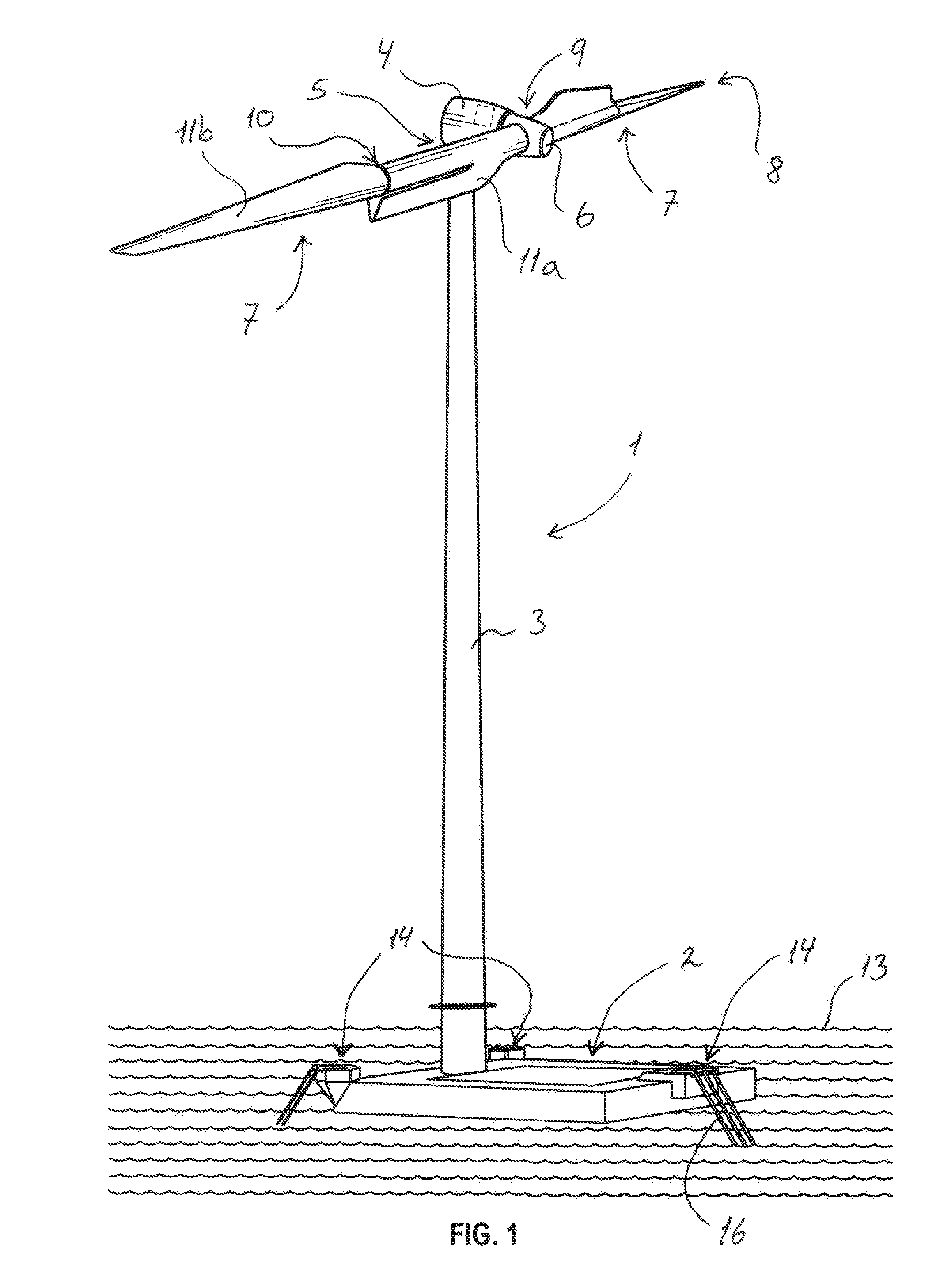
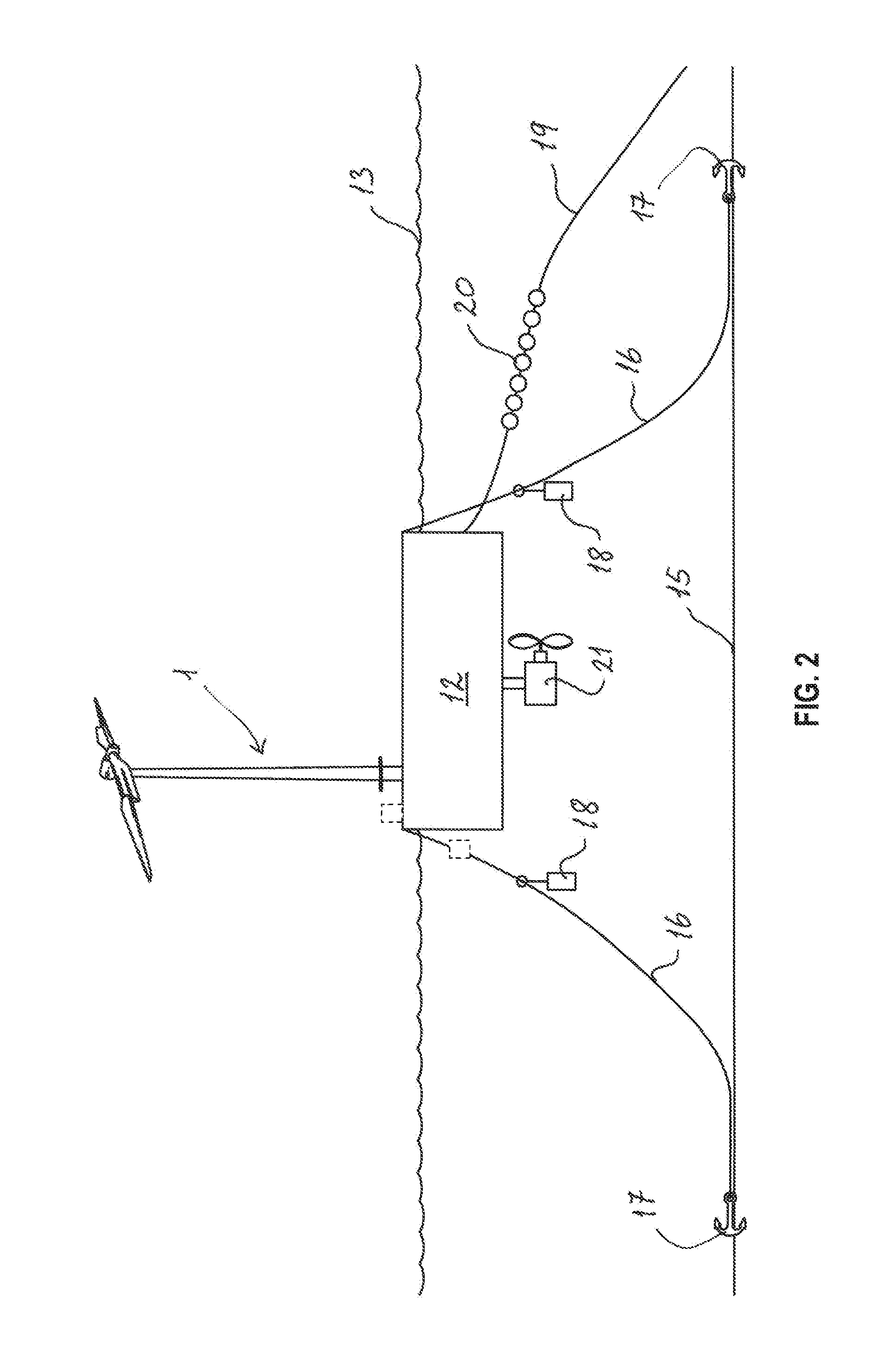
[0089]FIG. 2 shows a mooring system connected to the wind turbine structure of FIG. 1;

second embodiment

[0090]FIG. 3 shows the mooring system connected to the wind turbine structure of FIG. 1;

[0091]FIG. 4 shows a first exemplary graph of the global position of the wind turbine structure in a horizontal direction relative to the global position in a vertical direction;

[0092]FIG. 5 shows a second exemplary graph of the global positions shown in FIG. 4 in a time domain; and

[0093]FIG. 6 shows a third exemplary graph of the mooring force of the mooring system relative to the global position in the horizontal position.

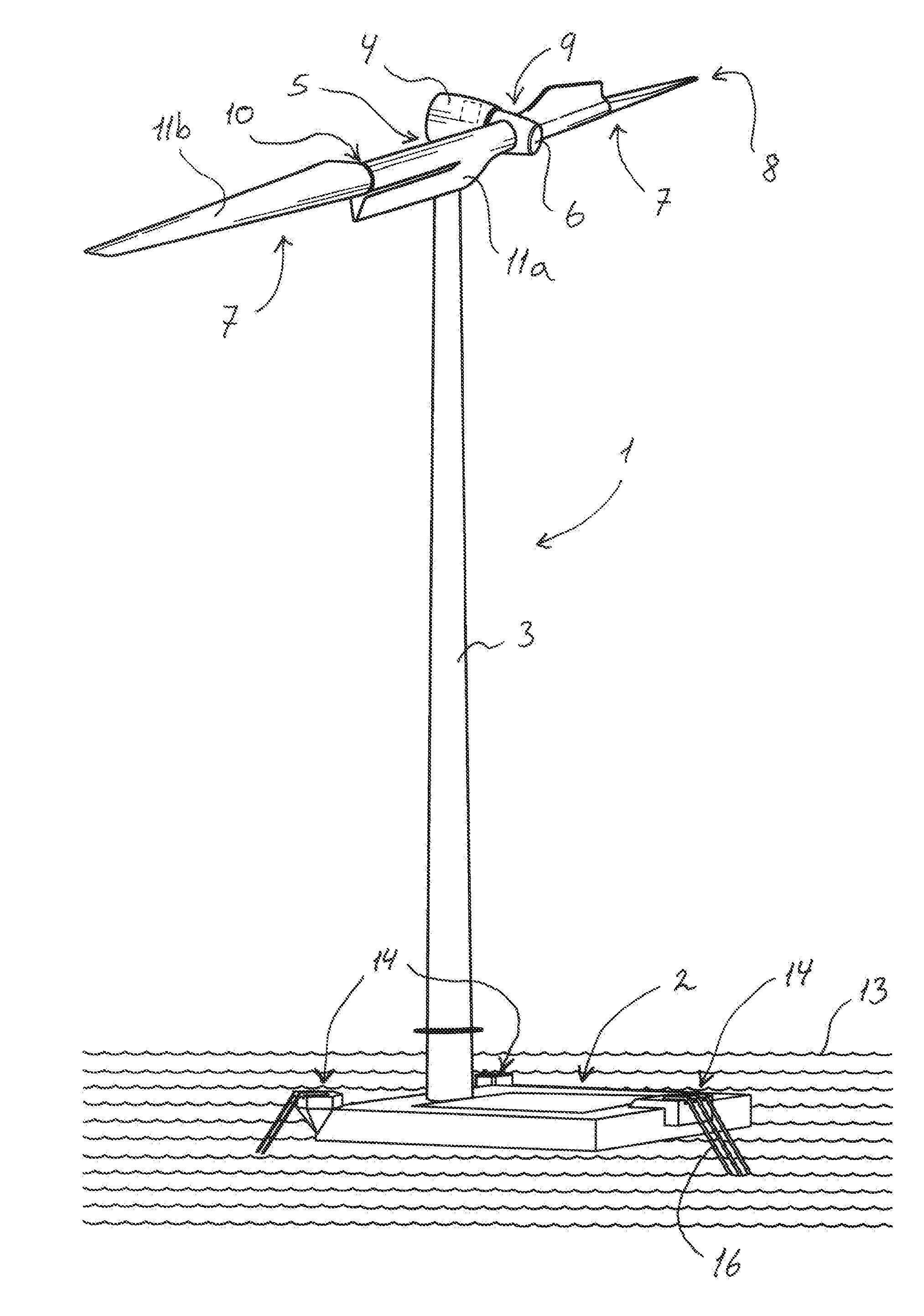
[0094]In the following text, the figures will be described one by one and the different parts and positions seen in the figures will be numbered with the same numbers in the different figures. Not all parts and positions indicated in a specific figure will necessarily be discussed together with that figure.


PUM


Abstract

The present invention relates to a wind turbine structure comprising a wind turbine tower with a nacelle arranged on the top to which a rotor hub with one or more rotatable mounted wind turbine blades are mounted which form a rotor plane. A floating foundation is mounted to the bottom of the wind turbine tower and the pitch and / or yaw system are used to regulate the position of the wind turbine structure. A control unit detects the relative movement of the wind turbine structure in two axial directions and activates the pitch or yaw system to move the wind turbine structure into an equilibrium position. This reduces the directional movement of the wind turbine structure so that it remains in a stable equilibrium position. This also reduces the oscillating movement and tension forces in the anchor chains.

Description

[0001]The application claims the benefit of Danish Application No. PA 2014 70213 filed Apr. 14, 2014 and PCT / DK2015 / 050065 filed Mar. 24, 2015, which are hereby incorporated by reference in their entirety as if fully set forth herein.FIELD OF THE INVENTION[0002]The present invention relates to a wind turbine structure comprising:[0003]a wind turbine tower having a top and a bottom,[0004]a nacelle arranged on top of the wind turbine tower,[0005]a rotor hub rotatably mounted to the nacelle,[0006]one or more pitchable wind turbine blades with a tip end and a blade root mounted to the rotor hub,[0007]a floatable foundation having an upper section mounted to the bottom of the wind turbine tower, wherein the foundation comprises a buoyant body configured to be installed at an offshore position,[0008]a mooring system having a plurality of catenary mooring lines, the mooring system is connected to the foundation and to at least one anchor arranged on a seabed, wherein the wind turbine struc...

Claims


Application Information

Patent Timeline
IPC IPC(8): F03D13/25G05D1/08F03D7/04B63B35/44F03D7/02F03D9/32
CPCF03D13/25F03D7/0228F03D9/32B63B2035/446B63B35/44G05D1/0875F03D7/042F03D7/0224F05B2240/93B63B21/50B63H25/42F03D3/068Y02E10/727Y02E10/74Y02E10/72
Inventor FRIEDRICH, MICHAELRUBAK, RUNE
Owner ENVISION ENERGY DENMARK
Learn More