
Method for controlling constant air volume of electric device adapted to exhaust or supply air

a technology of electric devices and constant air volume, which is applied in the direction of lighting and heating apparatus, heating types, instruments, etc., can solve the problems of affecting the ventilation efficiency of electric devices, increasing production costs, and increasing installation costs, so as to save production costs and simplify the structure of products , the algorithm is simpl

Active Publication Date: 2017-02-09
ZHONGSHAN BROAD OCEAN
View PDF2 Cites 6 Cited by
  • Summary
  • Abstract
  • Description
  • Claims
  • Application Information

AI Technical Summary

Benefits of technology

The invention provides a method for controlling a constant air volume using a motor body excluding the controller. The components for achieving the constant air volume control are integrated on the main control circuit board of the system controller, saving production costs and simplifying the product structure. The method uses a simple algorithm and does not require the microprocessor to have powerful computing capacity, reducing production costs. The method allows for the microprocessor to receive or preset a target air volume, compare it with known air volume points, and use interpolation to calculate a constant air volume control function to ensure the motor operates in accordance with the target air volume. The motor body employed is equipped with no controller, and components for realizing the method are principally integrated in the main control circuit board of the system controller.

Problems solved by technology

The method increases the production cost, and a dysfunction of the air flowmeter may result in control failure.
Other methods for controlling the constant air volume require monitoring of static pressure to adjust the rotational speed, or require strong computing capacity of the MCU of the motor controller, all of which increase the production cost.
This arrangement complicates the installation and affects the ventilation efficiency of the electric device.

Method used


Image

  • Method for controlling constant air volume of electric device adapted to exhaust or supply air
  • Method for controlling constant air volume of electric device adapted to exhaust or supply air
  • Method for controlling constant air volume of electric device adapted to exhaust or supply air

Examples


example 1

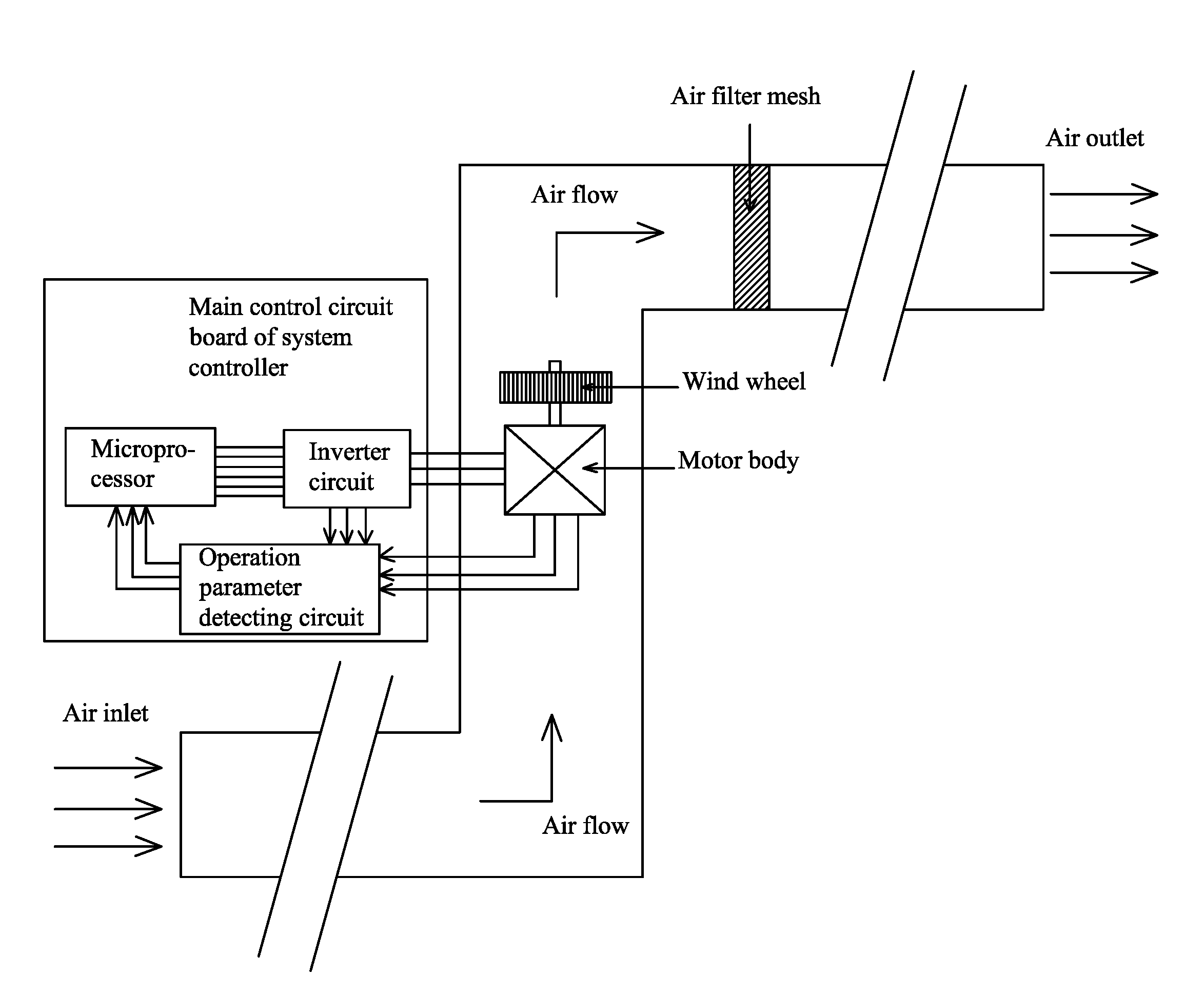
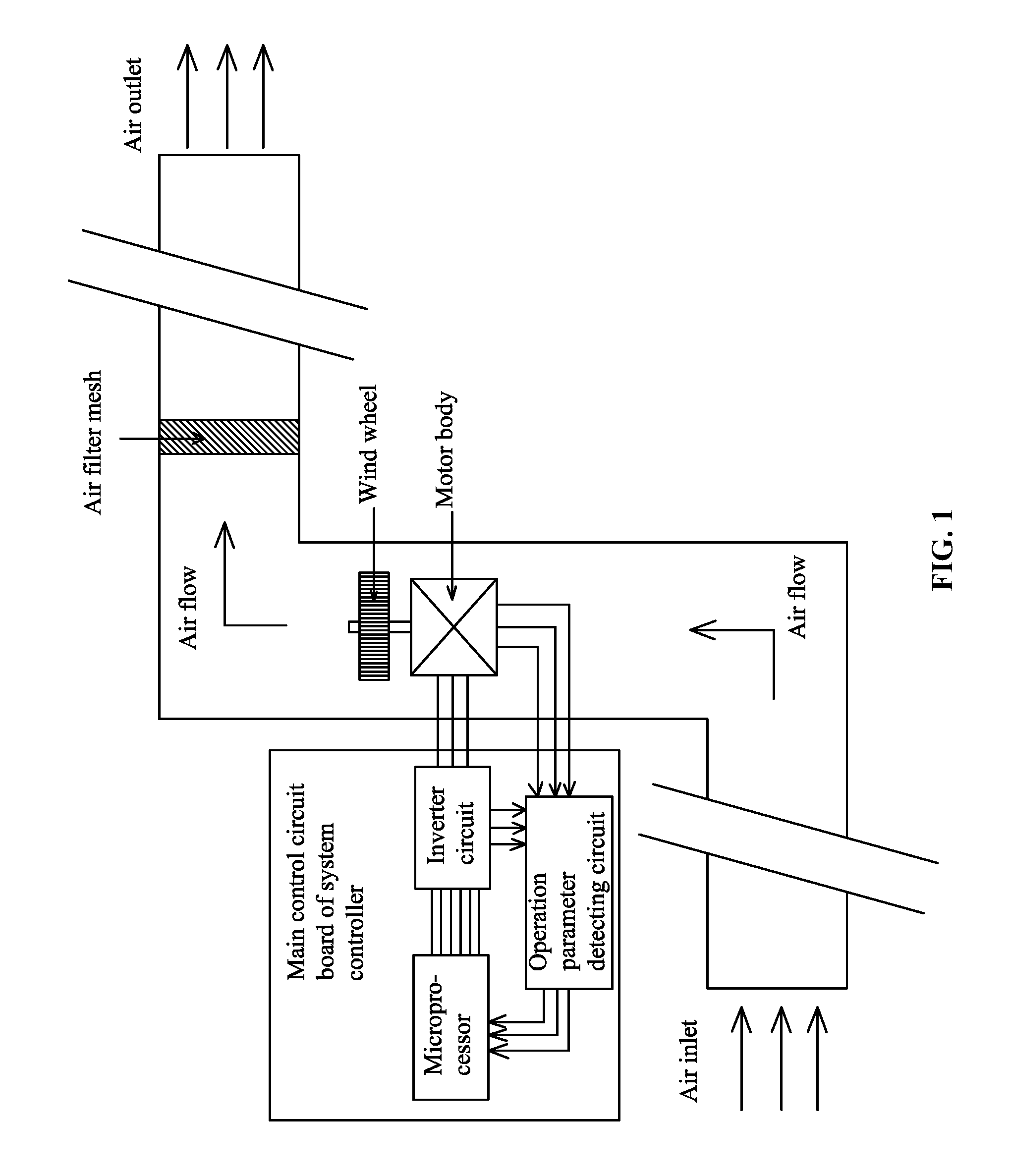
[0058]As shown in FIGS. 4-5, the electric device is an air conditioner provided with a system controller. The system controller is provided with a main control circuit board for realizing the function of the air conditioner. A microprocessor, an inverter circuit, and an operation parameter detecting circuit are arranged on the main control circuit board. The operation parameter detecting circuit inputs real-time operation parameters of the motor into the microprocessor. An output terminal of the microprocessor controls the inverter circuit, and an output terminal of the inverter circuit is connected to the coil winding.

[0059]As shown in FIG. 6, a method for controlling a constant air volume in an air conditioning system by direct power control is illustrated. The motor drives a wind wheel and comprises: a stator assembly and a permanent magnet rotor assembly. The microprocessor, the inverter circuit, a bus current detecting circuit, a bus voltage detecting circuit, and an input powe...

example 2

[0082]As shown in FIGS. 10-11, the electric device applying the method for control the constant air volume is a lampblack presser. The lampblack presser comprises a system controller which is provided with a main control circuit board for realizing the function of the lampblack presser. A microprocessor, an inverter, an operation parameter detecting circuit, a dependent power circuit, a gear input circuit, and a display circuit are arranged on the main control circuit board. The gear input circuit and the display circuit are connected to the microprocessor, the operation parameter detecting circuit inputs the real-time operation parameters of the motor into the microprocessor, an output terminal of the microprocessor controls the inverter circuit, and the output terminal of the inverter circuit is connected to the coil winding. In the figures, the operation parameter detecting circuit is a three phase current detecting circuit which is able to calculate the rotor position by measuri...

example 3

[0096]As shown in FIG. 13, the electric device is the lampblack presser. The lampblack presser comprises a system controller which is provided with a main control circuit board for realizing the function of the lampblack presser. A microprocessor, an inverter, an operation parameter detecting circuit, a dependent power circuit, a gear input circuit, and a display circuit are arranged on the main control circuit board. The gear input circuit and the display circuit are connected to the microprocessor, the operation parameter detecting circuit inputs the real-time operation parameters of the motor into the microprocessor, an output terminal of the microprocessor controls the inverter circuit, and the output terminal of the inverter circuit is connected to the coil winding. In the figures, the operation parameter detecting circuit is a Hall sensor which is mounted on the motor body for detecting the rotor position and able to detect the rotor position via the operation parameter detect...


PUM


Abstract

A method for controlling air volume of an electric device to be constant, the device being adapted to exhaust or supply air, the method including: A) establishing M constant air volume control functions Qi=F(n) corresponding to M air volume points CFMi in the microprocessor of the system controller; B) allowing the microprocessor to receive or preset a target air volume IN-CFM; C) starting the motor, when the motor operates in a stable state, comparing M air volume points CFMi with the target air volume IN-CFM, and ensuring that the target air volume IN-CFM falls within two known air volume points CFMi and CFMi−1; D) using the two known air volume points CFMi and CFMi−1 to calculate a constant air volume control function Q0=F(n) corresponding to the target air volume IN-CFM by interpolation method; and E) controlling a motor parameter Q0 and a rotational speed n.

Description

CROSS-REFERENCE TO RELATED APPLICATIONS[0001]This application is a continuation-in-part of International Patent Application No. PCT / CN2015 / 077456 with an international filing date of Apr. 24, 2015, designating the United States, now pending, and further claims priority benefits to Chinese Patent Application No. 201410598667.6 filed Oct. 29, 2014. The contents of all of the aforementioned applications, including any intervening amendments thereto, are incorporated herein by reference. Inquiries from the public to applicants or assignees concerning this document or the related applications should be directed to: Matthias Scholl P. C., Attn.: Dr. Matthias Scholl Esq., 245 First Street, 18th Floor, Cambridge, Mass. 02142.BACKGROUND OF THE INVENTION[0002]Field of the Invention[0003]The invention relates to a method for controlling constant air volume of an electric device adapted to exhaust or supply air.[0004]Description of the Related Art[0005]Typically, an air flowmeter is directly in...

Claims


Application Information

Patent Timeline
Patent Type & Authority Applications(United States)
IPC IPC(8): F24F11/047G05B17/02F24F11/75
CPCF24F11/047F24F2011/0061G05B17/02F24F11/63F24F11/75Y02B30/70
Inventor WANG, JIZHONGZHOU, YIQIAOZHANG, ZHENGHU, GEZHANG, XIANSHENGZHAO, YONG
Owner ZHONGSHAN BROAD OCEAN
Learn More