Evaporator having vertical arrangement of header pipe for vehicle air conditioner

a technology of header pipe and evaporator, which is applied in the direction of defrosting, domestic cooling apparatus, application, etc., can solve the problems of difficult to increase the heat transfer area for the same entire area, and achieve the effect of preventing condensation water, maximizing heat exchange area, and preventing condensation water

Inactive Publication Date: 2017-02-09
DONGHWAN IND CORP
View PDF5 Cites 11 Cited by
  • Summary
  • Abstract
  • Description
  • Claims
  • Application Information

AI Technical Summary

Benefits of technology

[0028]According to the evaporator having a vertical arrangement of header pipes for a vehicle air conditioner of the present invention, since the tubes are horizontally arranged, it is possible to maximize a heat transfer area from the same area of the entire evaporator and to provide the maximum efficiency of heat exchange at the same level.
[0029]Further, the guide bodies of the drain guide provide channels for cold air and the baffle boards, and collect and drop condensate water included in cold air by blocking the cold air, so it is possible to prevent condensate water produced on the surfaces of the tubes from scattering.
[0030]Therefore, since scattering of condensate water is provided even though tubes are horizontally arranged, it is possible to manufacture an evaporator without a limitation on the arrangement direction of tubes.

Problems solved by technology

Therefore, since tubes and heat-dissipating fins are only vertically arranged in the existing evaporators to discharge condensate water produced on the surfaces of the tubes and heat-dissipating fins, it is difficult to increase the heat transfer area for the same entire area.

Method used


Image

  • Evaporator having vertical arrangement of header pipe for vehicle air conditioner
  • Evaporator having vertical arrangement of header pipe for vehicle air conditioner
  • Evaporator having vertical arrangement of header pipe for vehicle air conditioner

Examples


Embodiment Construction

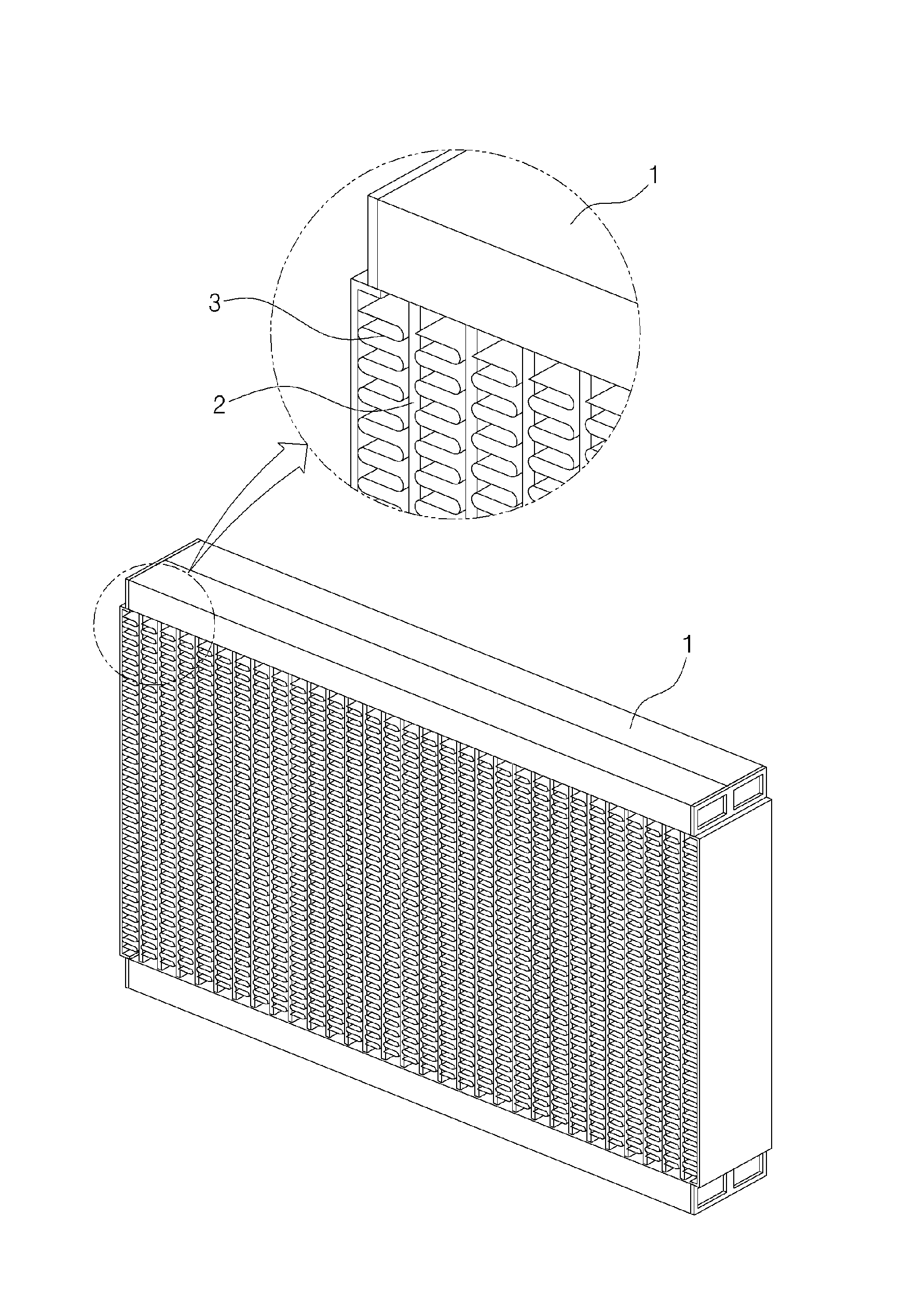
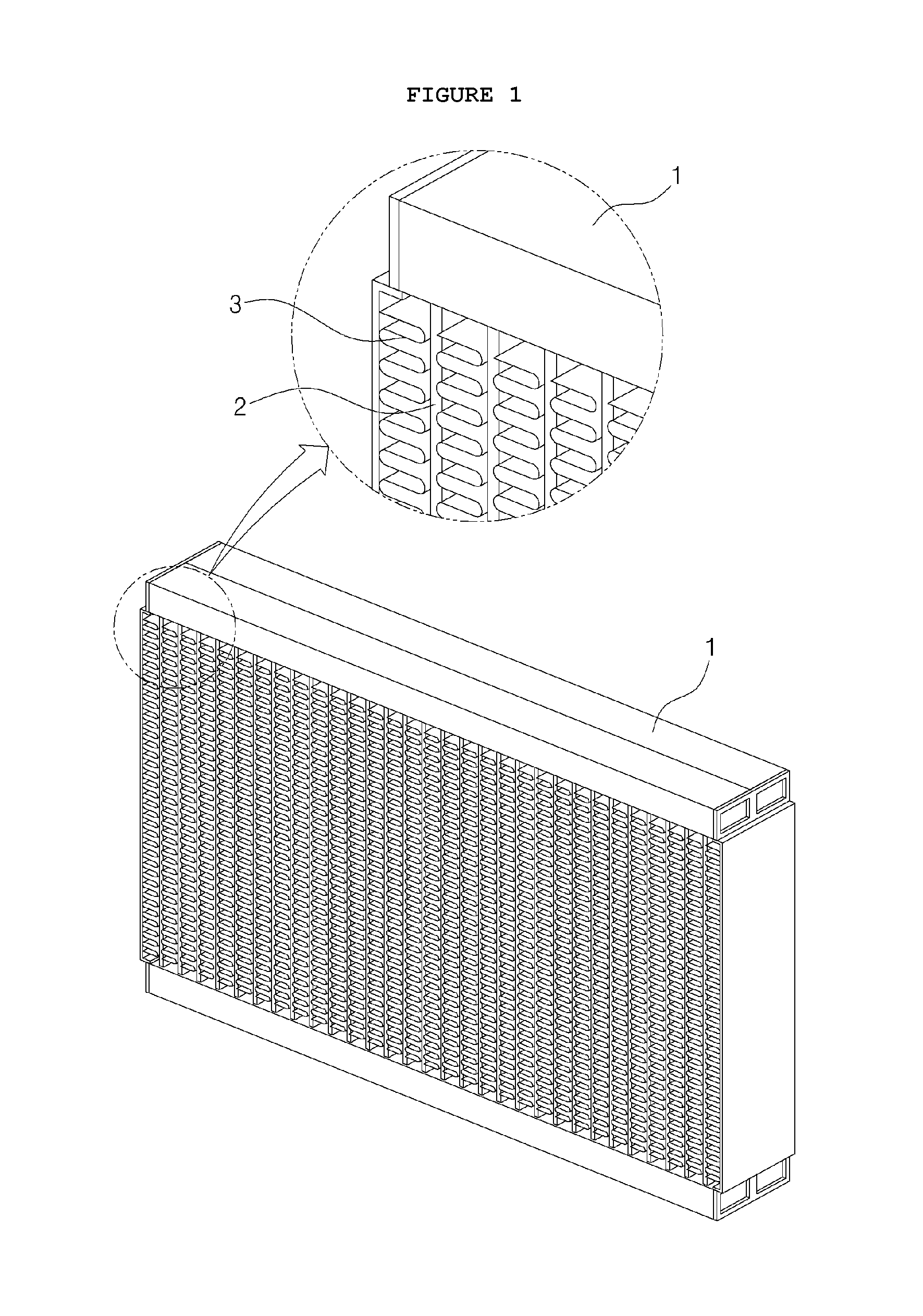
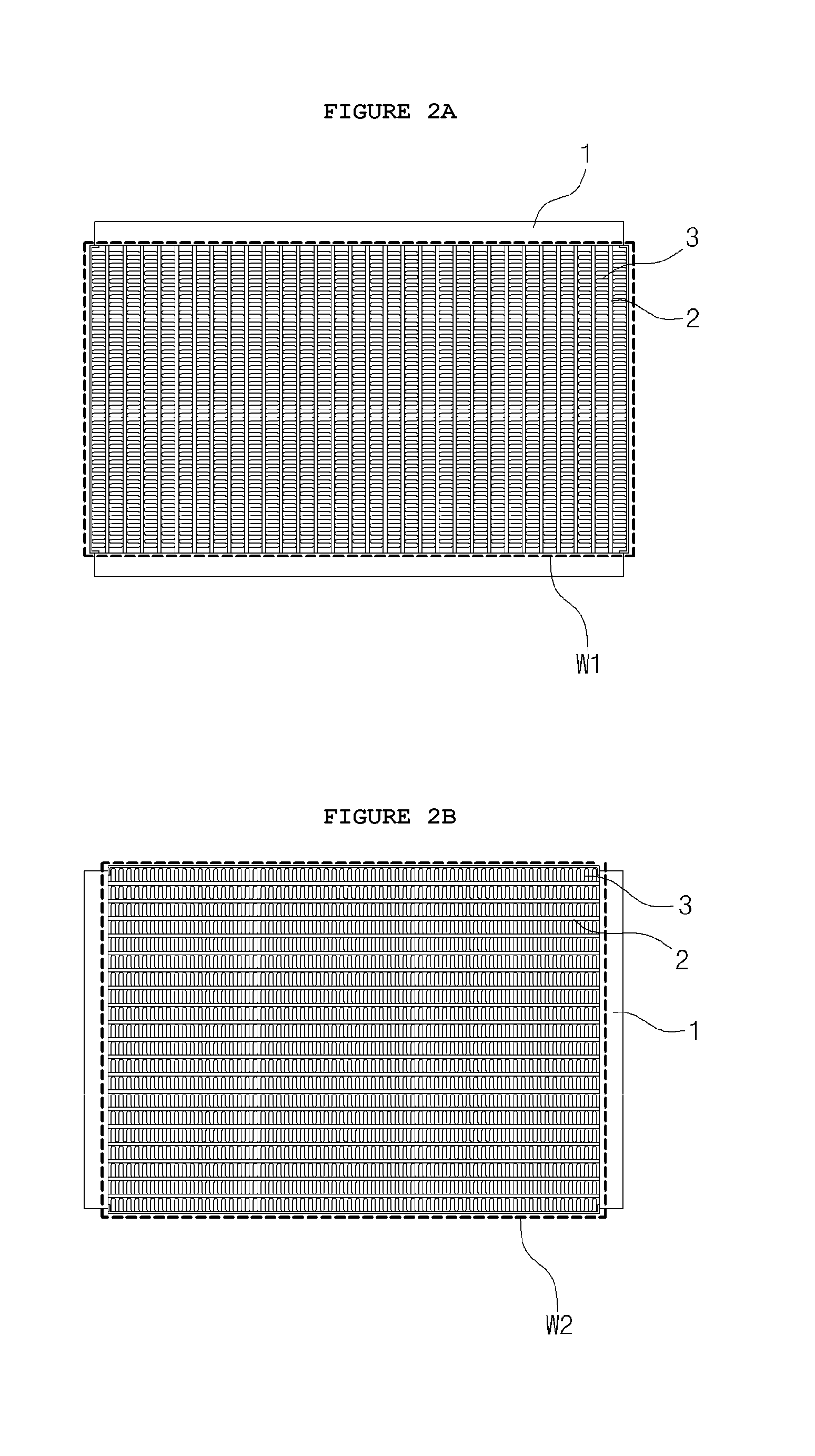
[0039]Exemplary embodiments of the present invention will be described more fully hereinafter with reference to the accompanying drawings. In the following description of the present invention, detailed descriptions of known functions and components incorporated herein will be omitted.

[0040]Embodiments of the present invention may be changed and modified in various ways, so that specific embodiments are shows in the drawings as examples and will be described in detail in this specification or application. However, it should be understood that embodiments according to spirit of the present invention are not limited to the specific embodiments, but include all modifications, equivalents, and substitutions included in the spirit and the scope of the present invention.

[0041]It should be understood that when one element is referred to as being “connected to” or “coupled to” another element, it may be connected directly to or coupled directly to another element or be connected to or coupl...


PUM


Abstract

The present invention provides an evaporator having a vertical arrangement of header pipes for a vehicle air conditioner, the evaporator including: a pair of header pipes disposed to face each other with a gap therebetween, providing a circulation path for a coolant supplied in the cooling cycle, and discharging the coolant that has exchanged heat; a plurality of tubes laterally arranged between the pair of header pipes to communicate with the header pipes, connected in a longitudinal direction of the header pipes, and allowing a coolant flowing inside through inlets of the header pipes to exchange heat with air while flowing in a zigzag pattern toward outlets of the header pipes; and heat-dissipating fins disposed among the tubes and dissipating heat of vaporization from the tubes while passing the air supplied from the fan.

Description

CROSS-REFERENCE TO RELATED APPLICATION[0001]This application claims priority to Korean Patent Application No. KR 10-2015-0109551 filed on Aug. 3, 2015 and all the benefits accruing therefrom under 35 U.S.C. §119, the contents of which are incorporated by reference in their entirety.BACKGROUND OF THE INVENTION[0002]Field of the Invention[0003]The present invention relates to an evaporator of an air conditioner and, more particularly, to an evaporator for a vehicle air conditioner wherein the evaporator has a large heat transfer area compared with existing evaporators by vertically arranging header pipes.[0004]Description of the Related Art[0005]In general, vehicles are equipped with an air-conditioning system for supplying fresh air into the interior, which is contaminated by the breath of passengers, the external atmospheric state, and a change in temperature of the external air, and for maintaining a pleasant internal environment by keeping the interior temperature at a level suita...

Claims


Application Information

Patent Timeline
Patent Type & Authority Applications(United States)
IPC IPC(8): F25B39/00F25D21/14
CPCF25B39/00F25B39/02F25D21/14F25B2339/02B60H1/3227F28F17/005F28D1/05391F28F1/126F28D2021/0085
Inventor KO, DONG HWAN
Owner DONGHWAN IND CORP
Why Eureka
Try Eureka