Lighting apparatus

a technology of lighting apparatus and projection apparatus, which is applied in the direction of lighting and heating apparatus, light source combinations, instruments, etc., can solve the problems of limiting the application of projection apparatus to modern wearable devices, image capture devices and/or detection devices, and achieve the effect of reducing the height and volume of the overall lighting apparatus, and small volum

Active Publication Date: 2017-02-09
EPIC INT TECH CO LTD
View PDF3 Cites 16 Cited by
  • Summary
  • Abstract
  • Description
  • Claims
  • Application Information

AI Technical Summary

Benefits of technology

[0004]One objective of present invention is to provide a lighting apparatus with small volume. Since an optical member is directly fixed on a substrate to cover plural lighting chips, the height and the volume of the overall lighting apparatus are reduced. Consequently, the lighting apparatus is suitably applicable to wearable devices.
[0034]In an embodiment, the structural light pattern is composed of random dots, symmetric non-interlaced stripes, asymmetric non-interlaced stripes, symmetric interlaced stripes or asymmetric interlaced stripes. When the plural lighting chips are synchronously driven by the driving circuit, a density of the random dots is increased or a distribution range of the random dots is widened, a density of the symmetric non-interlaced stripes or a light stripe density or a distribution range of the asymmetric non-interlaced stripes is increased, and a density of the symmetric interlaced stripes or a light stripe density or a distribution range of the asymmetric interlaced stripes is increased.

Problems solved by technology

Although the conventional projection apparatus for projecting plural images is effective to overcome the problem of projecting the single monotonous image, there are still some drawbacks.
For example, since the volume of this projection apparatus is large, the applications of the projection apparatus to modern wearable devices, portable communication devices, image capture devices and / or detecting devices are restricted.

Method used


Image

  • Lighting apparatus
  • Lighting apparatus
  • Lighting apparatus

Examples


first embodiment

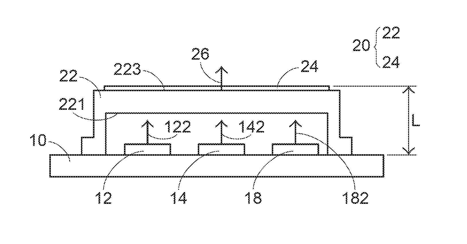
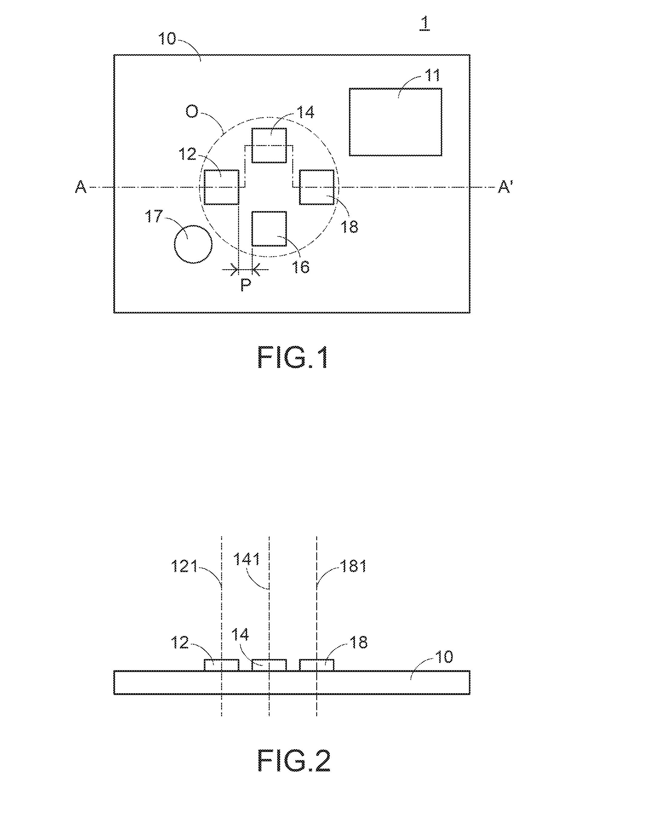
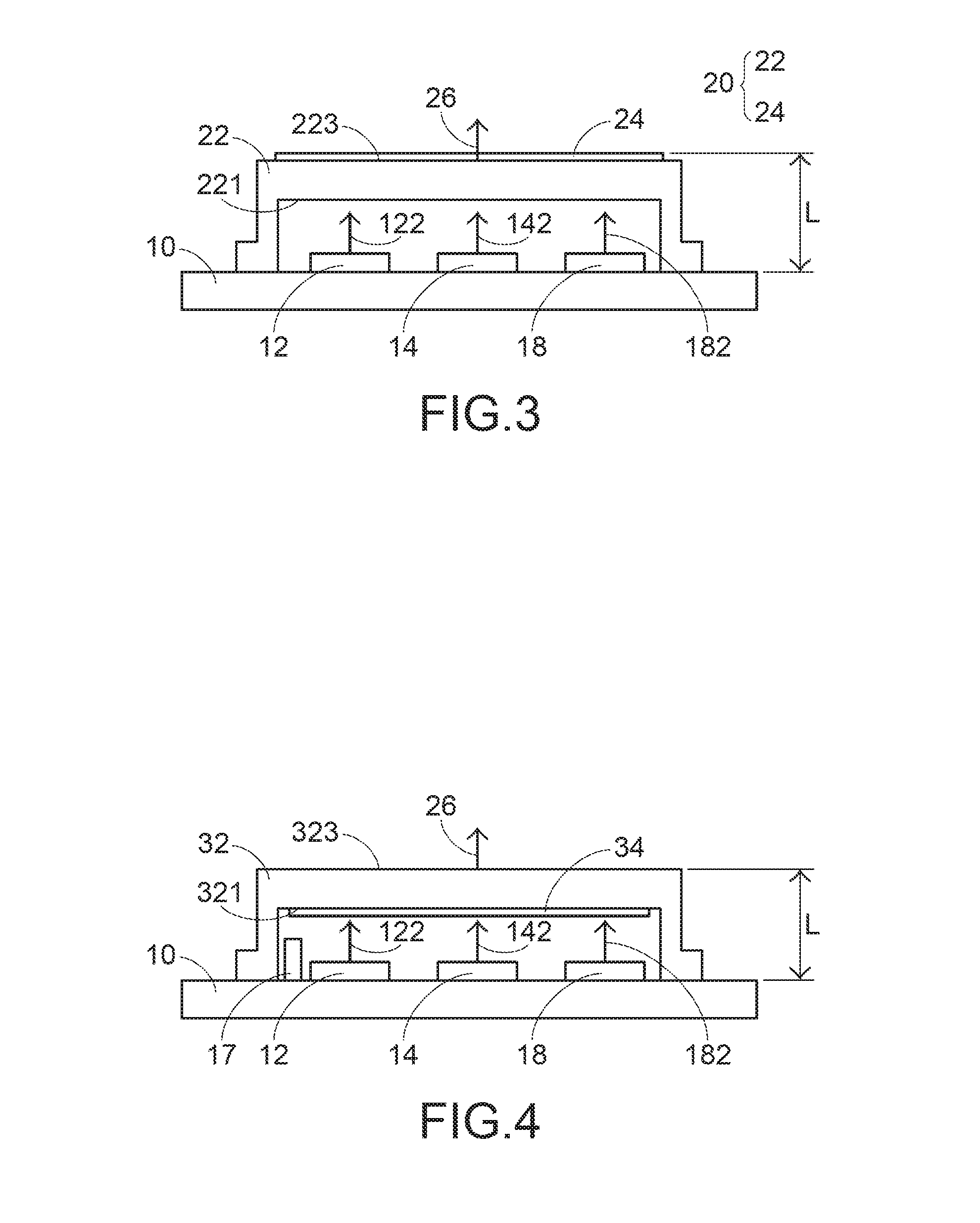
[0050]FIG. 3 is a schematic cross-sectional view illustrating the relationship between the substrate, the lighting chips and an optical member of a lighting apparatus according to the present invention. Please refer to FIGS. 1 and 3. The optical member 20 is fixed on the substrate 10. The optical member comprises a covering body 22 that covers the lighting chips 12, 14, 16 and 18. The covering body 22 has an inner surface 221 and an outer surface 223. The inner surface 221 faces the lighting chips 12, 14, 16 and 18. The outer surface 223 is exposed outside. The inner surface 221 and the outer surface 223 are flat surfaces or curvy surfaces. The inner surface 221 of the covering body 22 is separated from the lighting chips 12, 14, 16 and 18 by a specified distance. The optical member 20 further comprises an optical component 24. For example, the optical component 24 is a diffractive optical element (DOE) and used as a guiding lens. The optical component 24 is disposed on the outer su...

second embodiment

[0052]FIG. 4 is a schematic cross-sectional view illustrating the relationship between the substrate, the lighting chips and an optical member of a lighting apparatus according to the present invention. As shown in FIG. 4, the optical component 34 is disposed on the inner surface 321 of the covering body 32. In this embodiment, the distance L between the outer surface 323 of the covering body 32 and the surface of the substrate 10 that the lighting chips are mounted thereon is not larger than 3.0 mm. As mentioned above, the optical member with the covering body is disposed over the lighting chips to cover the lighting chips. After the laser beams from the lighting chips are received by the optical member, the laser beams are collimated and converted into the structural light pattern by the optical member. Consequently, the structural light pattern is outputted from the optical member. Moreover, the covering body of the optical member has a light outputting surface. The numerical ape...

third embodiment

[0053]FIG. 5 is a schematic cross-sectional view illustrating the relationship between the substrate, the lighting chips and an optical member of a lighting apparatus according to the present invention. As shown in FIG. 5, the optical member 40 further comprises a diffractive structure 44 and plural guiding lenses 48. The diffractive structure 44 is formed on the outer surface 423 of the covering body 42. The guiding lenses 48 are fixed on the inner surface 421 of the covering body 42. The guiding lenses 48 are coated films, or the guiding lenses 48 are optical structures that are directly formed on the covering body 42. The guiding lenses 48 are used for guiding the plural light beams 122, 142 and 182 from the lighting chips 12, 14 and 18 and the light beam from the lighting chip 16 (not shown). Moreover, in this embodiment, the photodiode 17 or the sensing component is not covered by the covering body 42. It is noted that the guiding lenses 48 are not restricted to the typical lig...


PUM


Abstract

A lighting apparatus includes an optical member with a diffractive optical element. The optical member is directly fixed on a substrate with plural lighting chips. When the lighting apparatus is applied to a laser diode module, the height and volume of the overall laser diode module are reduced. Consequently, the laser diode module is suitably applied to a small-size device.

Description

FIELD OF THE INVENTION[0001]The present invention relates to a lighting structure, and more particularly to a lighting apparatus for emitting a structural light.BACKGROUND OF THE INVENTION[0002]Taiwanese Utility Patent No. M490043 discloses a projection apparatus for projecting plural images. The projection apparatus comprises an outer frame, an optical source module and a diffractive optical element. The optical source module is installed within a lateral end of the outer frame. The diffractive optical element is disposed within the outer frame, and separated from the optical source module. The projection apparatus can project plural images. Consequently, the problem of projecting only a single virtual image by the conventional projection apparatus is overcome.[0003]Although the conventional projection apparatus for projecting plural images is effective to overcome the problem of projecting the single monotonous image, there are still some drawbacks. For example, since the volume o...

Claims


Application Information

Patent Timeline
Patent Type & Authority Applications(United States)
IPC IPC(8): G02B5/18F21K99/00F21V23/00F21V7/00F21V5/04
CPCG02B5/1866F21V7/0066F21V5/04F21Y2113/005F21K9/50F21Y2101/025F21V23/005H01S5/4093G01B11/2513G02B27/20G02B27/425H01L25/0753H01S5/02255H01S5/02257H01S5/02253G03B21/2013G03B21/2033
Inventor CHERN, JYH-LONGYEN, CHIH-MING
Owner EPIC INT TECH CO LTD
Why Eureka
Try Eureka