Interface device for the connection and the passage of an electric route through an airtight wall of an aircraft

Active Publication Date: 2017-02-09
AIRBUS OPERATIONS SAS
View PDF4 Cites 0 Cited by
  • Summary
  • Abstract
  • Description
  • Claims
  • Application Information

AI Technical Summary

Benefits of technology

The patent text describes a way to make sure that products are lightweight, cost-effective, and easy to assemble and fit together. This way can help solve the problem that some products are heavy and expensive to put together.

Problems solved by technology

This usual solution comprising two separate systems, namely a first system for providing the mechanical passage function between the first zone (for example, the pressurized zone) and the second zone (for example, the unpressurized zone) and a second system for providing the electrical connection function, has disadvantages in terms of weight, cost and difficult assembly in particular.
This solution is therefore not the optimum.

Method used


Image

  • Interface device for the connection and the passage of an electric route through an airtight wall of an aircraft
  • Interface device for the connection and the passage of an electric route through an airtight wall of an aircraft
  • Interface device for the connection and the passage of an electric route through an airtight wall of an aircraft

Examples


Embodiment Construction

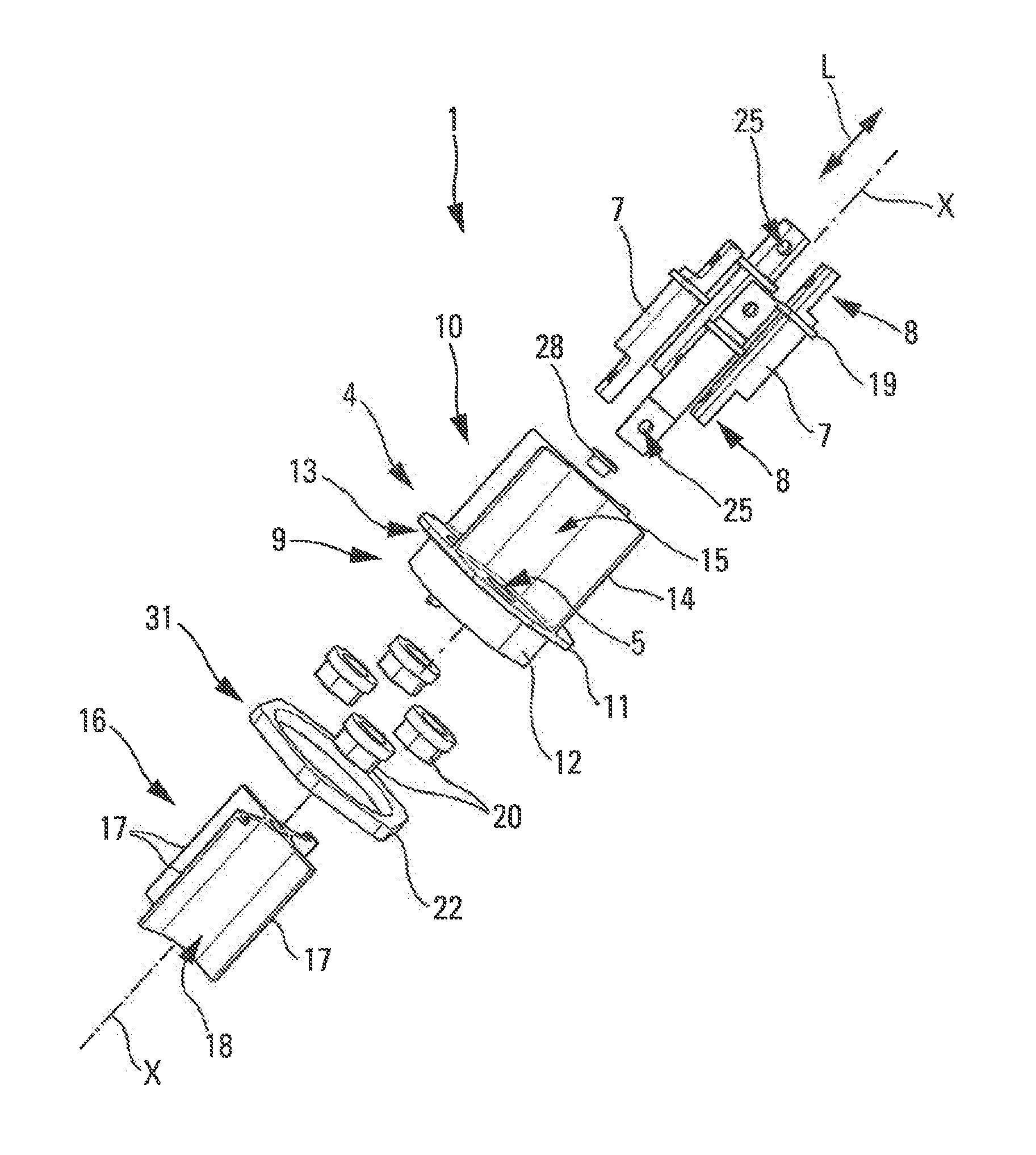
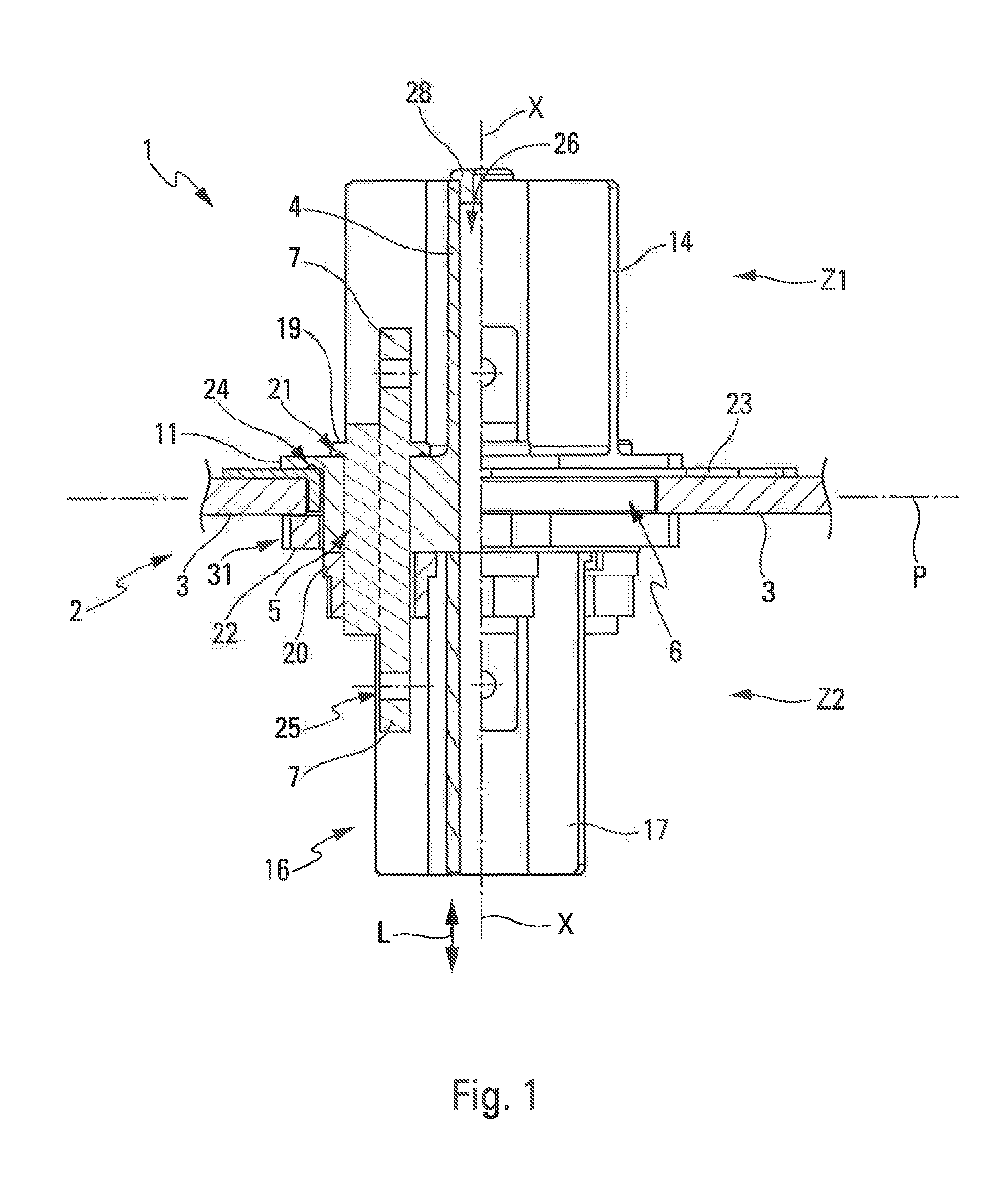
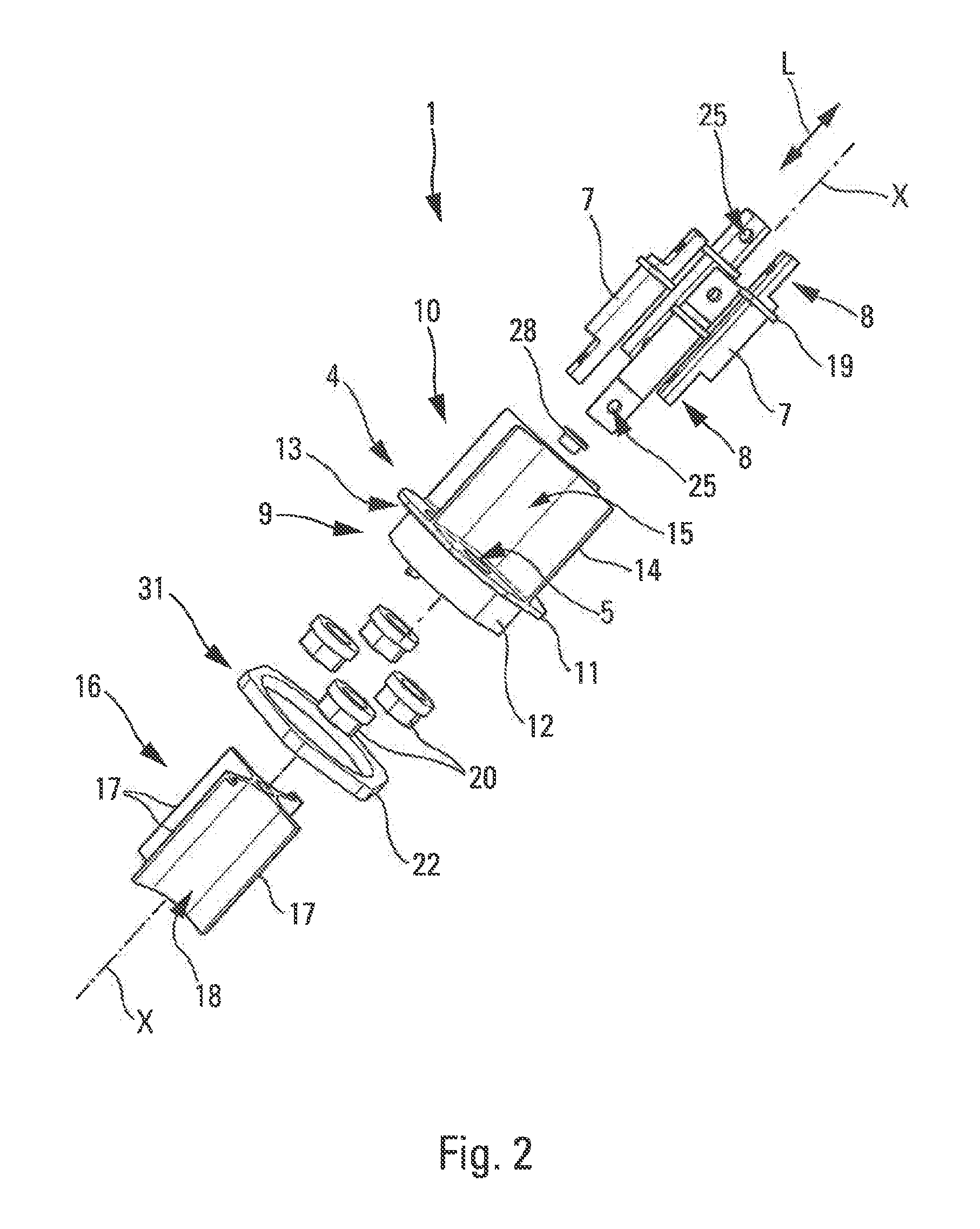
[0039]The interface device 1 represented diagrammatically in section in FIG. 1 and serving to illustrate the invention is intended to provide a connection and the passage of an electric route through a structural element 2 including at least a part of an airtight wall (or bulkhead) 3 of an aircraft (not shown).

[0040]More particularly, although not exclusively, this airtight wall 3 separates a pressurized zone Z1 of the aircraft from an unpressurized zone Z2.

[0041]The interface device 1 has a longitudinal axis X-X (defining a longitudinal direction L) that is an axis of symmetry (circular symmetry) for most of the components of the interface device 1.

[0042]In the FIG. 1 fixed position (or mounting position), the interface device 1 is mounted on the airtight wall 3 so that the longitudinal axis X-X is substantially orthogonal to a medium plane P of the airtight wall 3 at least in the vicinity of the mounting zone.

[0043]In accordance with the invention, the interface device 1 includes,...


PUM


Abstract

An interface device that includes a plastic part including at least one through-opening in a longitudinal direction, the plastic part being adapted to be fixed in an airtight manner into an opening in the wall. At least one metal shaft is arranged and fixed in the through-opening. The metal shaft has a connection element at each longitudinal end. The metal shaft is configured to provide electric connectivity from one side of the wall to the other in a fixed position of the interface device. At least one fixing element is adapted to fix the plastic part to the wall.

Description

CROSS-REFERENCES TO RELATED APPLICATIONS[0001]This application claims the benefit of the French patent application No. 1557528 filed on Aug. 4, 2015, the entire disclosures of which are incorporated herein by way of reference.BACKGROUND OF THE INVENTION[0002]The present invention concerns an interface device for the connection and the passage of an electric route through an airtight wall of an aircraft.[0003]The present invention notably applies to installing on an aircraft an electric route passing through an airtight wall (or bulkhead) separating a pressurized zone of the aircraft from an unpressurized zone.[0004]More particularly, although not exclusively, it is applied to a “G-route” power route representing an electrical power supply between a variable frequency generator (VFG) and the EPDC (electrical power distribution center) in the fuselage (for distribution of the electrical power supply to the equipment in the aircraft).[0005]To this end, there is generally provided a fir...

Claims


Application Information

Patent Timeline
IPC IPC(8): H01R25/00H01R43/00H01R43/26H01R13/52
CPCH01R25/006H01R13/5202H01R13/5205H01R2201/26H01R43/005H01R43/26H01R13/521B64D2221/00H01R13/746
Inventor FAGGELLA, DAVIDELAFRANCHIS, SAMSONCHAPOULIE, PHILIPPE
Owner AIRBUS OPERATIONS SAS
Why Eureka
Try Eureka