
Method and apparatus for hierarchical motion estimation using dfd-based image segmentation

a hierarchical motion and image segmentation technology, applied in image analysis, image enhancement, instruments, etc., can solve the problems of not taking advantage of multiple pixel-related segmentation information, huge memory requirements, etc., and achieve the effect of improving reliability and accuracy

Inactive Publication Date: 2017-02-09
THOMSON LICENSING SA
View PDF2 Cites 4 Cited by
  • Summary
  • Abstract
  • Description
  • Claims
  • Application Information

AI Technical Summary

Benefits of technology

The patent describes a method for estimating the motion of objects in an image or video. It uses a level-based motion estimation approach that filters out background noise and reduces computational complexity. The method also segmented the picture into different moving objects and stored the information to improve performance and reliability. The technical effects of this approach include improved reliability and accuracy in situations where different objects move at different speeds and directions, as well as efficient motion estimation for every pixel in the image.

Problems solved by technology

A challenging one is when motion is estimated for an image location where there are different objects moving at different speed and / or direction.
Unfortunately that method has inherent problems with periodic structures because pixels with same or similar colour but a certain distance apart may mislead the motion estimator.
In addition, this concept does not attempt to consider different motion.
However, since segmentation information is stored for the complete (subsampled) measurement window for every location a vector is estimated for, memory requirements can become huge (e.g. for the later, finer levels of the hierarchy).
Moreover, no advantage is taken of multiple pixel-related segmentation information being present as a result of overlapping measurement window positions.

Method used


Image

  • Method and apparatus for hierarchical motion estimation using dfd-based image segmentation
  • Method and apparatus for hierarchical motion estimation using dfd-based image segmentation
  • Method and apparatus for hierarchical motion estimation using dfd-based image segmentation

Examples


Embodiment Construction

[0046]Even if not explicitly described, the following embodiments may be employed in any combination or sub-combination.

[0047]I. Identifying Object Locations in the Complete Image—Whole-Frame Mode

[0048]I.1 Motion Estimation Type and Memory Requirements

[0049]The motion estimation method described in [4] includes segmentation of the measurement window and fits well the case of estimating motion vectors for pixels of interest (‘pixels-of-interest mode’) since location information—which is available for every pixel in the subsampled measurement window—needs to be stored only around the pixels of interest, and their number will typically be low. When estimating motion vectors for all picture elements in an image (‘whole-frame mode’) the same processing can be applied, i.e. location information obtained from motion estimation for every grid point or pixel for which a vector is estimated in a level of the hierarchy could be stored in the same way. This would require a storage space proport...


PUM


Abstract

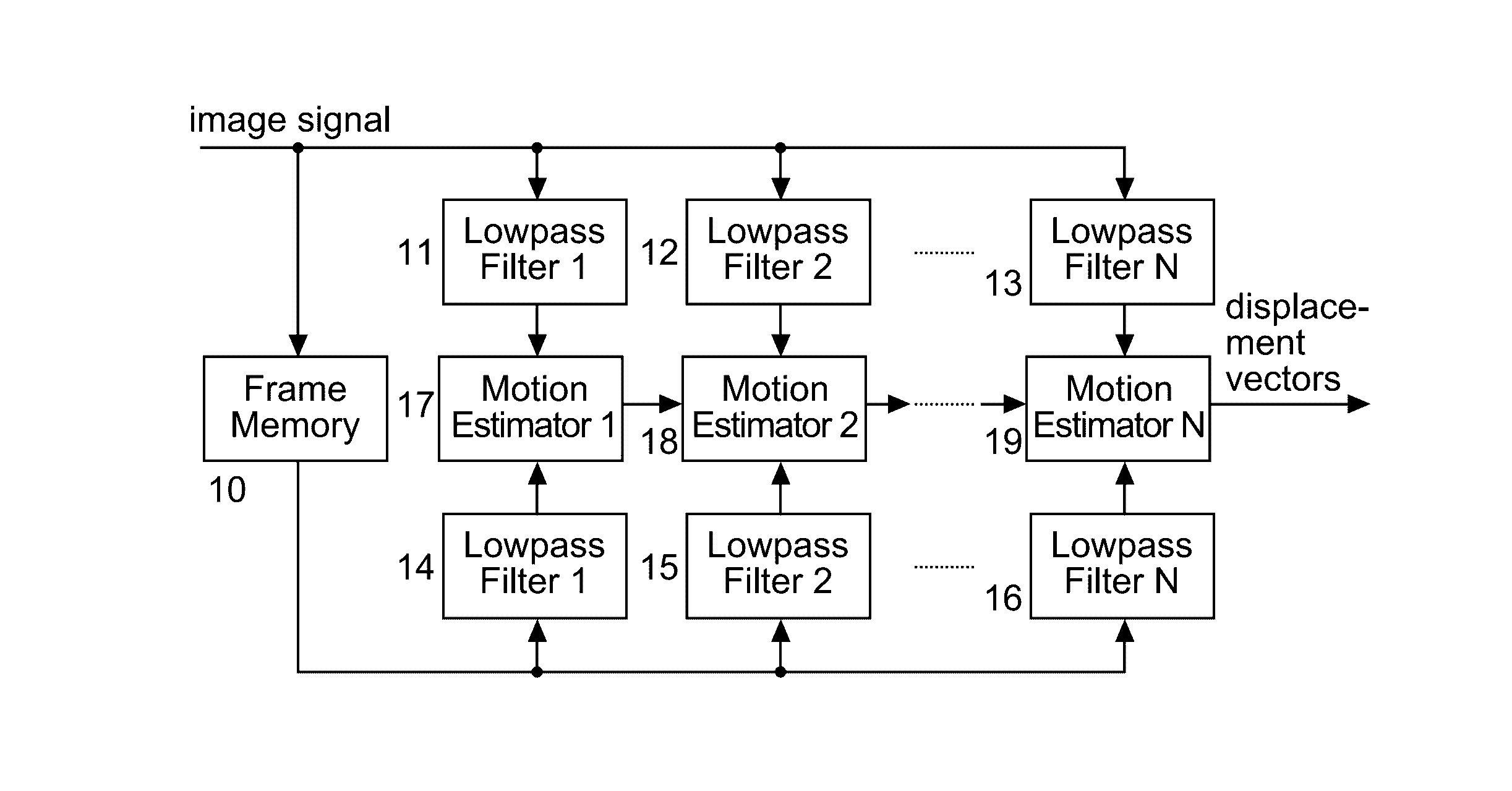
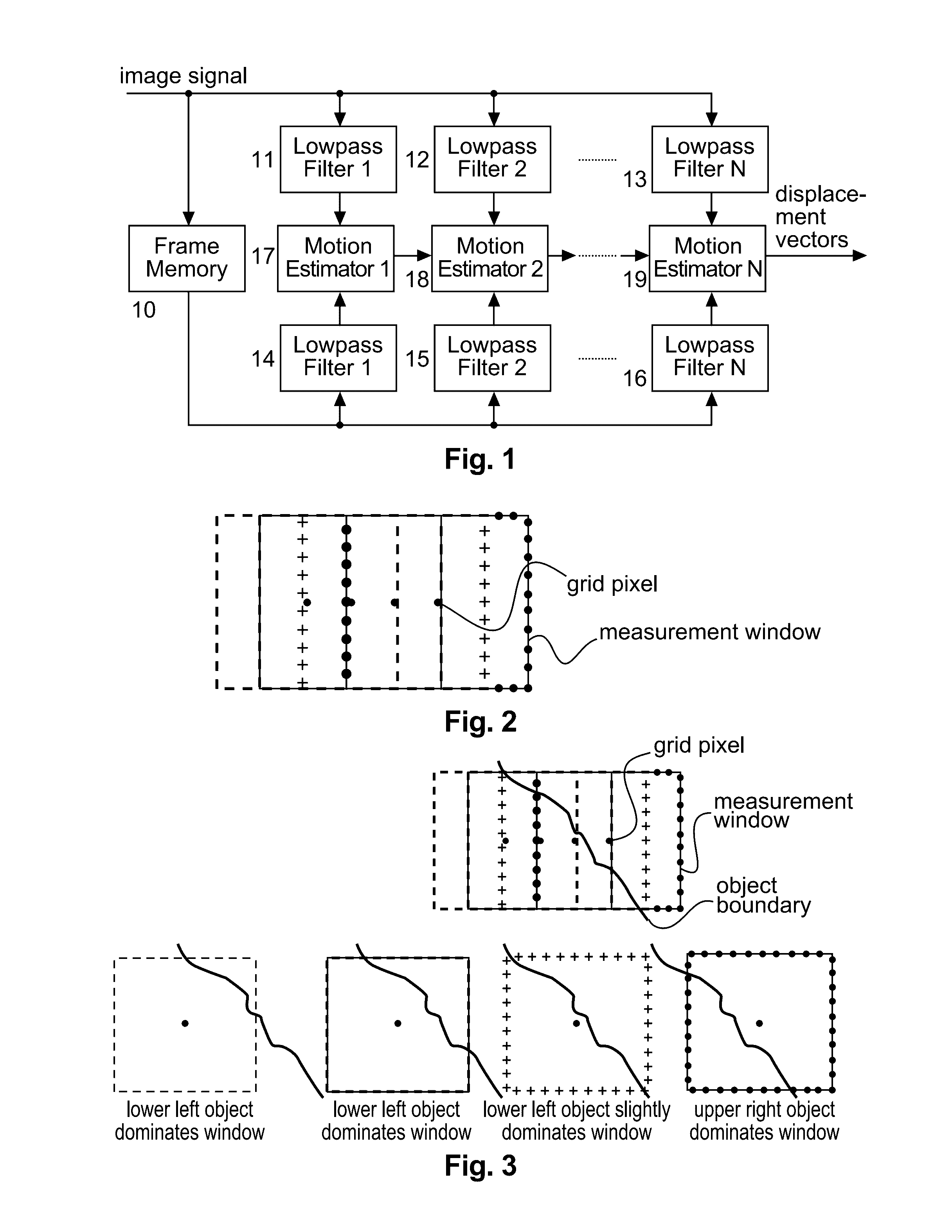
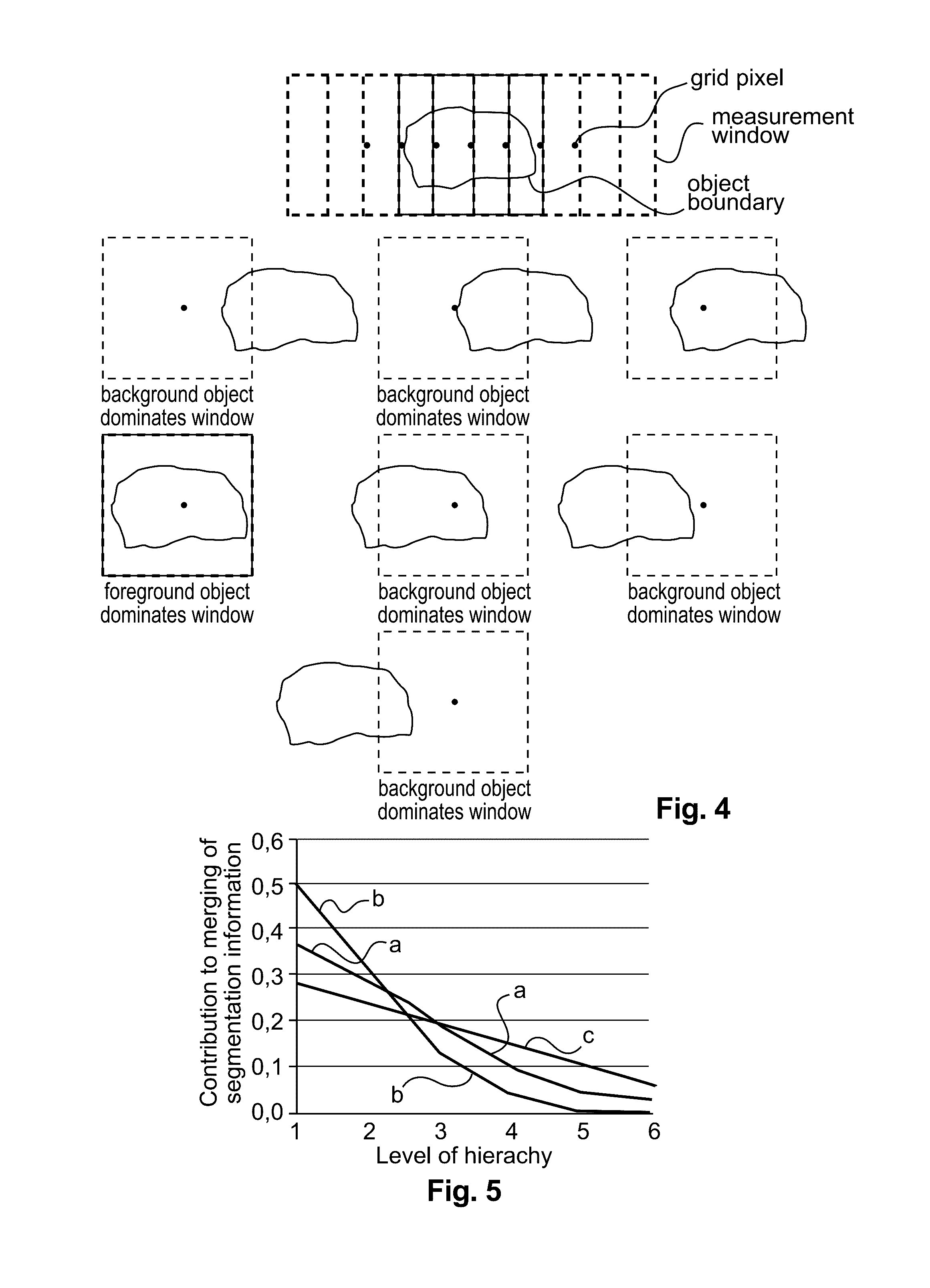
In hierarchical motion estimation, in each motion estimation hierarchy level, a pixel block matcher for comparing correspondingly sampled pixel values of a current image and a delayed previous image is used in order to compute a motion vector for every pixel. By evaluating displaced frame differences in the measurement window, a segmentation of the measurement window into different moving object regions is performed. The corresponding segmentation information is stored, and the stored segmentation information is used as an initial segmentation mask for motion estimation in the following finer level of the motion estimation hierarchy. In the following finer level of the motion estimation hierarchy an updated segmentation information is determined. This processing continues until the finest level of said motion estimation hierarchy is reached. The resulting segmentation information values of successive search window positions can be combined.

Description

TECHNICAL FIELD[0001]The invention relates to a method and to an apparatus for hierarchical motion estimation wherein a segmentation of the measurement window into different moving object regions is performed.BACKGROUND[0002]Estimation of motion between frames of image sequences is used for applications such as targeted content and in digital video encoding. Known motion estimation methods are based on different motion models and technical approaches such as gradient methods, block matching, phase correlation, ‘optical flow’ methods (often gradient-based) and feature point extraction and tracking. They all have advantages and drawbacks. Orthogonal to and in combination with one of these approaches, hierarchical motion estimation allows a large vector search range and is typically combined with block matching, cf. [1],[2]. In motion estimation a cost function is computed by evaluating the image signal of two image frames inside a measurement window.[0003]Motion estimation faces a num...

Claims


Application Information

Patent Timeline
IPC IPC(8): H04N19/53H04N19/57H04N19/513
CPCH04N19/53H04N19/57H04N19/521G06T2207/20016G06T7/207
Inventor HEPPER, DIETMAR
Owner THOMSON LICENSING SA
Learn More