Wireless power supply system and wireless power transmission system

a power supply system and wireless technology, applied in charging stations, transportation and packaging, rail devices, etc., can solve the problems of large amount of power required, adversely affecting nearby electronic devices, etc., and achieve the effect of reducing the leakage magnetic field

Active Publication Date: 2017-02-16
TDK CORPARATION
View PDF1 Cites 7 Cited by
  • Summary
  • Abstract
  • Description
  • Claims
  • Application Information

AI Technical Summary

Benefits of technology

[0017]As described above, according to the present invention, it is possible to provide a wireless power supply system and a wireless power transmission system with which a leakage magnetic field can be reduced effectively even if the relative position relationship of a moving body to a power transmitting coil changes.

Problems solved by technology

Meanwhile, in a case of applying the wireless power transmission technique to a charging apparatus in a power electronics apparatus, such as an electric vehicle, transmission of a large amount of power is required, and therefore, a large current needs to be supplied to a coil.
Accordingly, the intensity of a leakage magnetic field formed in a location away from the coil is high, which might cause an electromagnetic disturbance that adversely affects nearby electronic devices and so on.

Method used


Image

  • Wireless power supply system and wireless power transmission system
  • Wireless power supply system and wireless power transmission system
  • Wireless power supply system and wireless power transmission system

Examples


Embodiment Construction

[0022]A detailed description of a mode for implementing the present invention (embodiment) will be given with reference to the drawings. Note that, in the description, the same reference characters are used for the same elements or elements having the same functions, and a duplicated description is omitted.

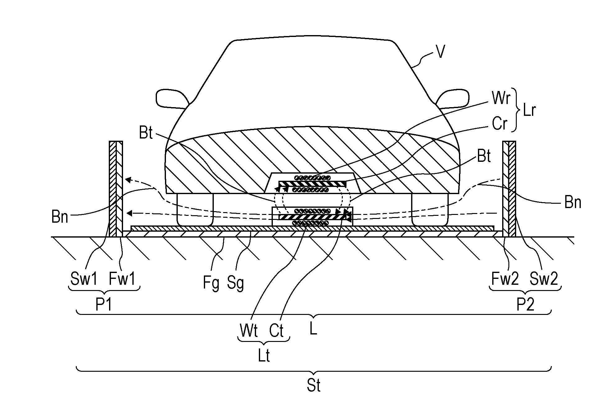
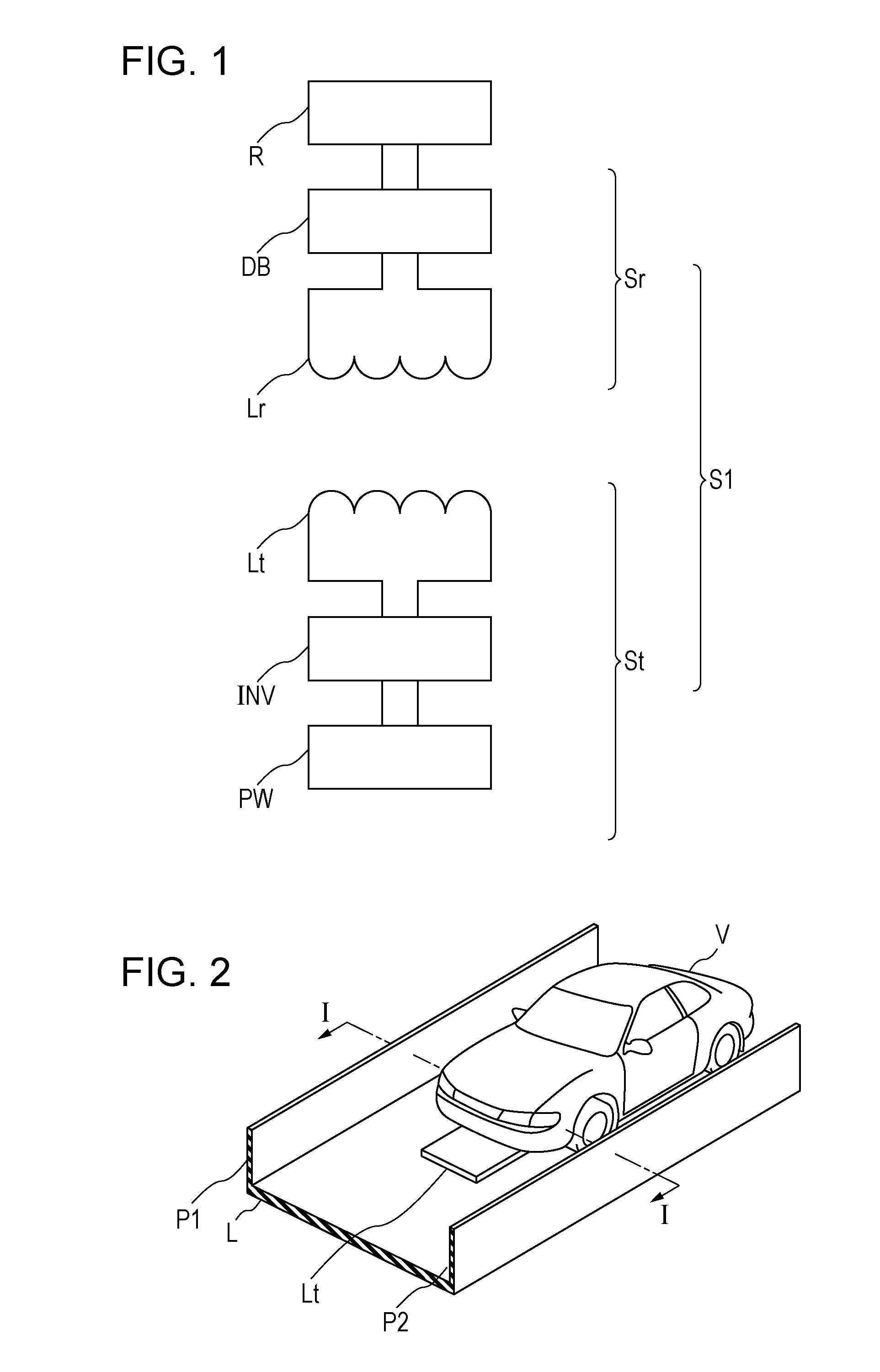
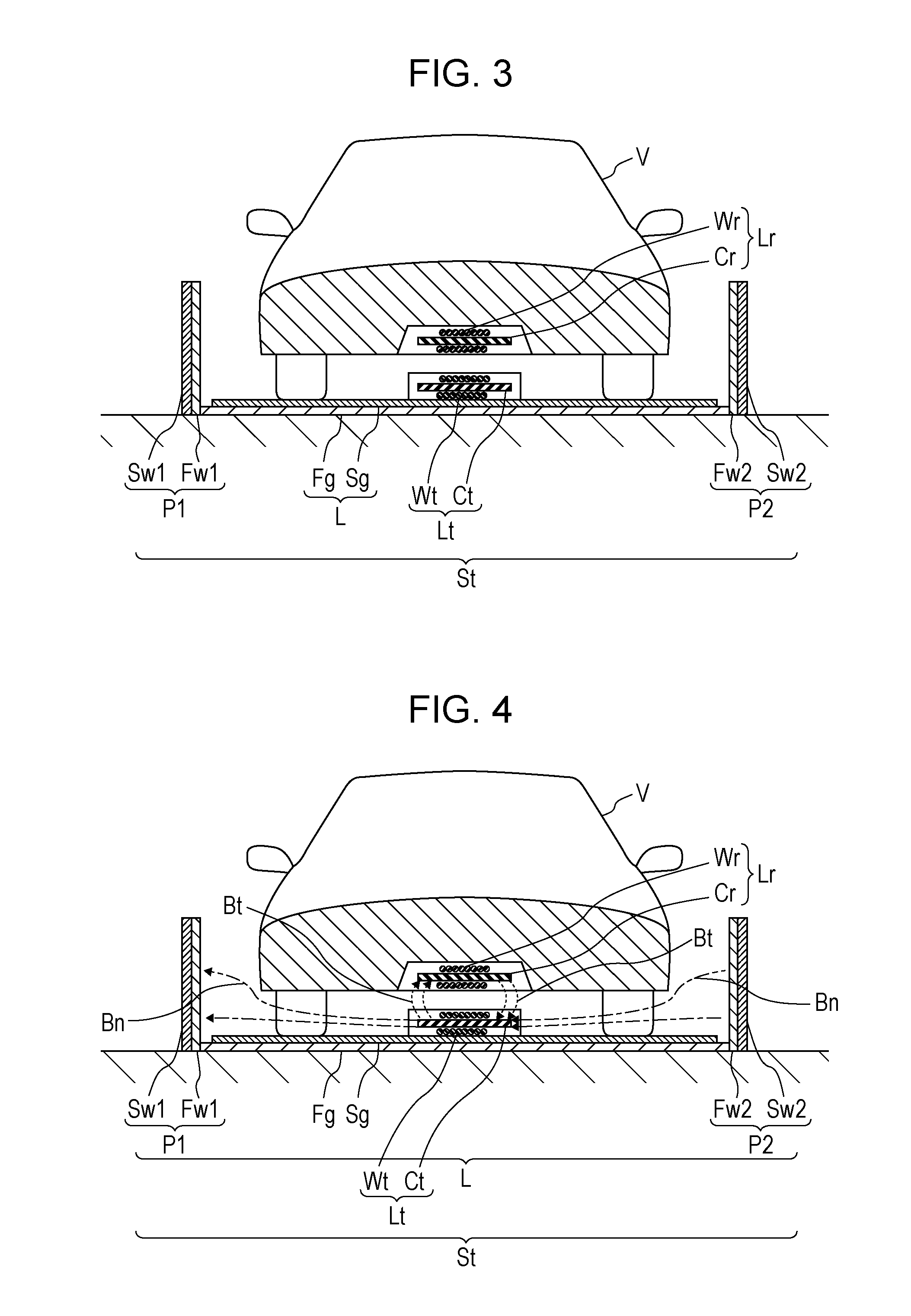
[0023]First, an overall configuration of a wireless power transmission system S1 according to a preferred embodiment of the present invention will be described with reference to FIG. 1 to FIG. 3. FIG. 1 is a schematic system configuration diagram illustrating an electrical configuration of the wireless power transmission system according to a preferred embodiment of the present invention and a load. FIG. 2 is a perspective view illustrating a power transmitting coil in a wireless power supply system, a travel lane, and electromagnetic shielding walls in the wireless power transmission system according to a preferred embodiment of the present invention together with a moving body. ...


PUM

PropertyMeasurementUnit
widthaaaaaaaaaa
conductiveaaaaaaaaaa
heightaaaaaaaaaa

Abstract

A wireless power supply system is a wireless power supply system provided with a travel lane for wirelessly transmitting power to a moving body and includes a power transmitting coil that is disposed such that the axial direction of the coil is substantially parallel to the width direction of the travel lane, and electromagnetic shielding walls that are disposed on the respective sides of the travel lane in the extension direction of the travel lane.

Description

TECHNICAL FIELD[0001]The present invention relates to a wireless power supply system and a wireless power transmission system for wirelessly transmitting power to a moving body.BACKGROUND ART[0002]Recently, a wireless power transmission technique using an electromagnetic induction interaction between a primary (power transmitting) coil and a secondary (power receiving) coil that face each other to transmit power without a physical contact, such as a cable, has been drawing attention, and the extensive use thereof in a power supply apparatus for charging a secondary battery mounted on an electric vehicle (EV) or a hybrid electric vehicle (HEV) is anticipated.[0003]Such a wireless power transmission technique enables power transmission without a physical contact, and therefore, is expected to be applied to an external power supply apparatus for a travelling electric vehicle or hybrid electric vehicle. For example, Patent Literature 1 discloses a technique for efficiently transmitting ...

Claims


Application Information

Patent Timeline
Patent Type & Authority Applications(United States)
IPC IPC(8): B60L11/18H01F38/14H02J7/02H02J50/12H01F27/36
CPCB60L11/182B60L11/1824H02J50/12B60L2230/10H02J7/025H01F38/14H01F27/365B60L5/005B60M1/36B60M7/003Y02T90/12Y02T90/14H02J50/70B60L53/30B60L53/122H01F27/36Y02T10/7072Y02T10/70H01F27/361H02J50/10
Inventor CHIYO, NORITAKATERASAKI, YASUHIROSUZUKI, MITSUNARI
Owner TDK CORPARATION
Why Eureka
Try Eureka