This helps you quickly interpret patents by identifying the three key elements:
Problems solved by technology
Method used
Benefits of technology
Benefits of technology
The patent describes a system that detects the secondary current and uses it to control the supply of energy from an auxiliary power source. The system ensures that the energy is supplied to the ignition plug without interruption, and prevents any change in the secondary current. This results in a highly reliable ignition device that can maintain stable ignition for an arbitrary period. The system is easy to install and is not affected by changes in voltage or other factors.
Problems solved by technology
This results in an increase in manufacturing cost, an increase in size of the device, and a decrease in reliability.
Method used
Image
Click on the blue label to locate the original text in one second.
Reading with bidirectional positioning of images and text.
Examples
first embodiment
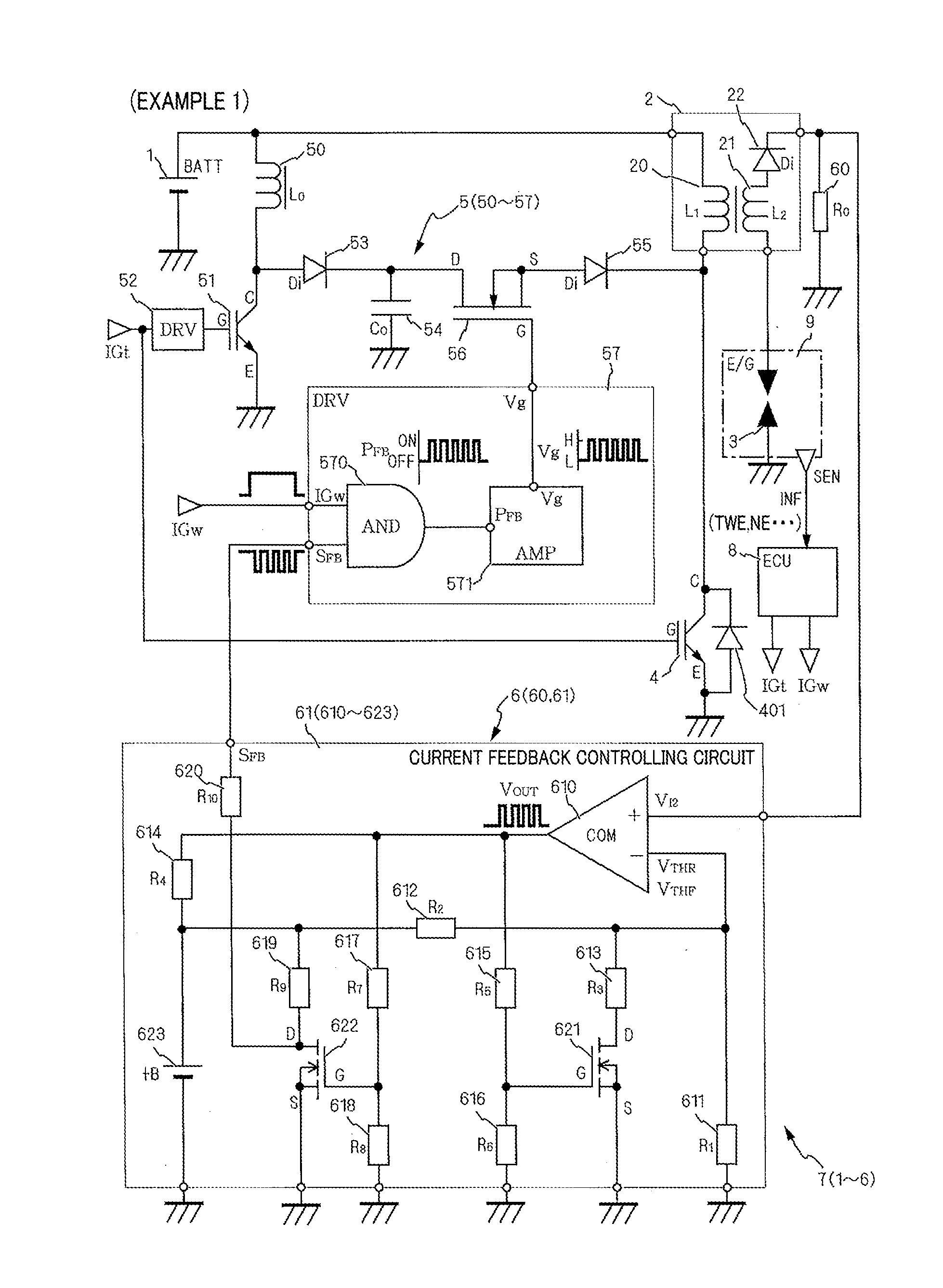
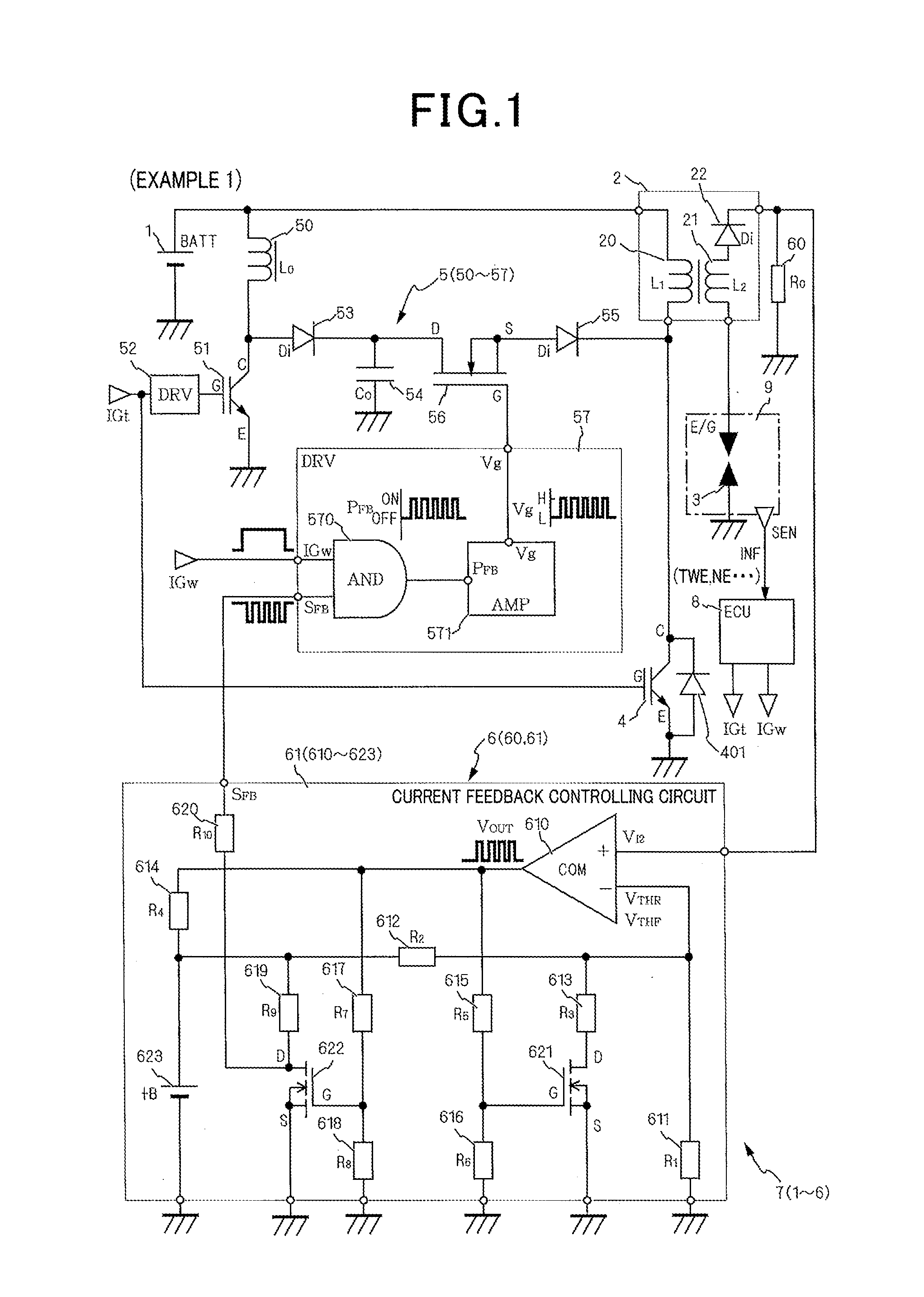
[0040]With reference to FIG. 1, hereinafter is described an ignition device 7 in a first embodiment of the present invention. It should be noted that, in this application document, positive and negative signs indicate directions of electric current, and magnitude of electric current is indicated on the basis of the magnitude of an absolute value of electric current. Increase or rise of electric current refers to increase in absolute value of electric current, and decrease or lowering of electric current refers to decrease in absolute value of electric current.
[0041]The ignition device 7 of the present invention is provided to each cylinder of an internal combustion engine 9 and ignites an air-fuel mixture introduced into a combustion chamber, not shown, by generating spark discharge.
[0042]The ignition device 7 includes a direct-current power source 1, an ignition coil unit 2, an ignition plug 3, an ignition switch 4, an auxiliary power source 5, and a secondary current feedback cont...
second embodiment
[0158]With reference to FIG. 6, hereinafter is described an ignition device 7b according to a second embodiment of the present invention.
[0159]It should be noted that the description of configurations similar to the above embodiment is omitted, and that only configurations of a feedback controlling means 6b and a driving driver 57b, which are characteristic of the present invention, are described.
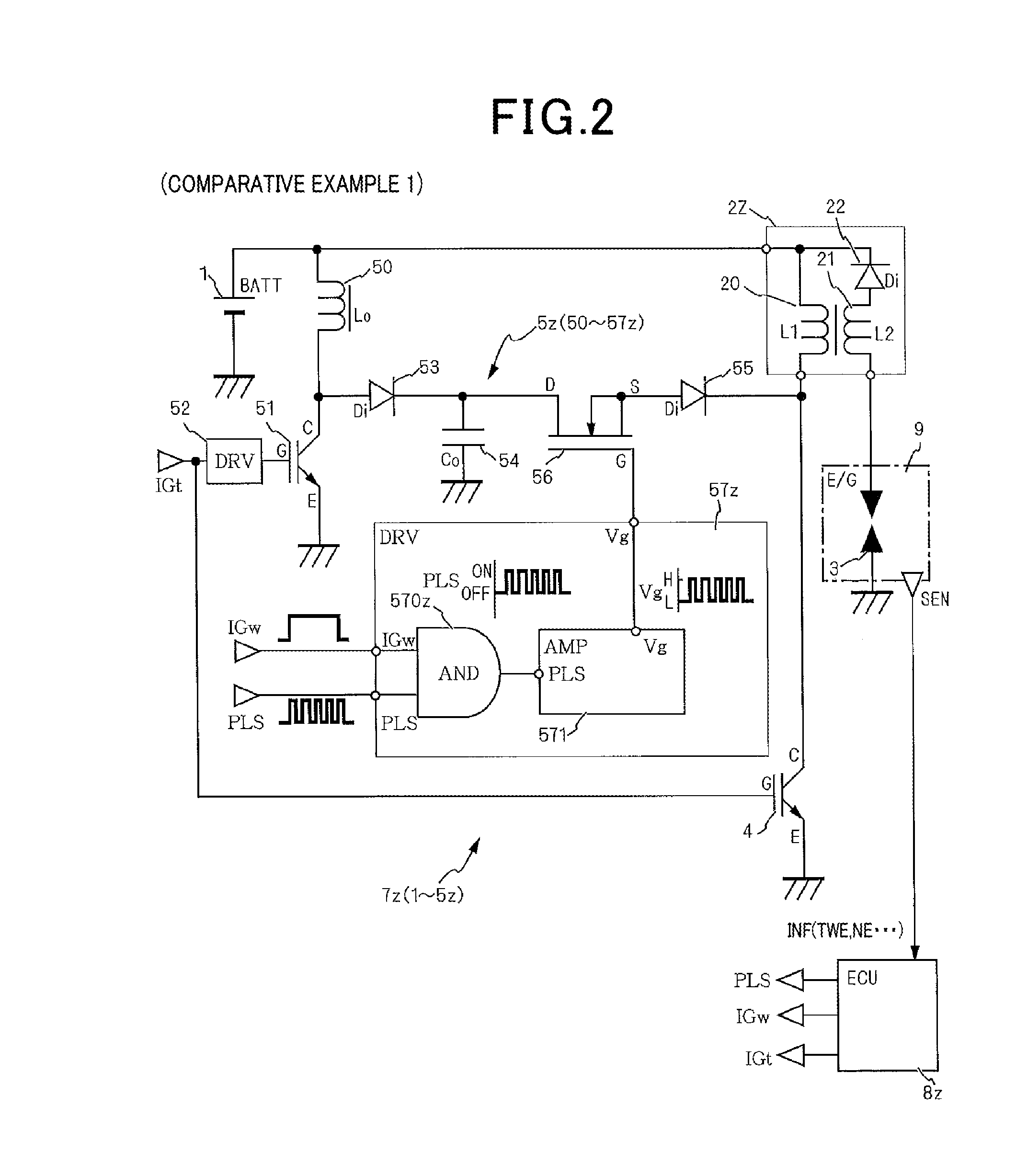
[0160]Example 1 shows the following configuration having hysteresis. That is, the limit changeover switch 621 is driven using the output VOUT of the comparator to change the voltage inputted to the inverting input (−). On the other hand, in present embodiment, the secondary current detection voltage V12 is inputted to the inverting input (−), and the control voltage +B of the control source 623 is proportionally divided by voltage dividing resistors 611b and 612b and inputted to the non-inverting input (+). Further, in present embodiment, the output Vout of the comparator 610 is fed back th...
third embodiment
[0163]With reference to FIG. 7, hereinafter is described an ignition device 7c according to a third embodiment of the present invention.
[0164]The present embodiment includes the configurations of the above embodiment, and differs in that the secondary current feedback controlling means 6c includes a secondary current feedback circuit 61c, a discharge blow-off detecting means IGFU62, a secondary current command value calculating means 63, and a secondary current learning means 64. The discharge blow-off detecting means IGFU62 detects the occurrence of discharge blow-off of the secondary current I2 due to in-cylinder airflow in the combustion chamber, and sends a discharge blow-off signal IGF. The secondary current command value calculating means 63 calculates a secondary current target value I2I as a target, according to the operating condition. The secondary current learning means 64 corrects the secondary current target value I2I as a target, according to whether the discharge blow...
PUM
Abstract
An ignition device at least equipped with a DC power source, an ignition coil unit, a spark plug, an ignition switch, and an auxiliary power source, wherein the auxiliary power source is at least equipped with a discharge energy accumulating means, a discharge switch, and a discharge driver. The ignition device is further equipped with a secondary-current feedback controlling means comprising a secondary current detecting means for detecting a secondary current flowing during the ignition coil unit discharge period, and a secondary current feedback control circuit-for determining an upper limit and a lower limit for the secondary current from binary threshold values, and driving so as to open and close the discharge switch on the basis of the determination results. Furthermore, energy is introduced from the auxiliary power source without switching the polarity of the secondary current.
Description
TECHNICAL FIELD[0001]The present invention relates to an ignition device igniting an internal combustion engine, and especially relates to the ignition device including an auxiliary power source ensuring continuous discharge.BACKGROUND ART[0002]PTL1 shows, aside from a usual ignition device, an ignition coil including a DC-DC converter which inputs discharge energy to the ignition coil on the secondary side.[0003]The ignition device of PTL1 extends the discharge continuation period after starting discharge by supplying power to an ignition plug through the secondary coil of the ignition coil, and thereby attempts to ensure stable ignition.[0004]However, regarding the conventional ignition device shown in PTL1, because an electric current is directly supplied to the secondary coil of the ignition coil where the extremely high voltage is generated, the DC-DC converter needs to be formed by high-voltage elements. This results in an increase in manufacturing cost, an increase in size of...
Claims
Application Information
Patent Timeline
Application Date:The date an application was filed.
Publication Date:The date a patent or application was officially published.
First Publication Date:The earliest publication date of a patent with the same application number.
Issue Date:Publication date of the patent grant document.
PCT Entry Date:The Entry date of PCT National Phase.
Estimated Expiry Date:The statutory expiry date of a patent right according to the Patent Law, and it is the longest term of protection that the patent right can achieve without the termination of the patent right due to other reasons(Term extension factor has been taken into account ).
Invalid Date:Actual expiry date is based on effective date or publication date of legal transaction data of invalid patent.

