
Method of controlling fuel cell system, method of controlling fuel cell automobile, and fuel cell automobile

a fuel cell and automobile technology, applied in secondary cell servicing/maintenance, fuel energy technology, batteries, etc., can solve the problems of not being able to interrupt the electrical power the voltage of the inverter terminal cannot be increased to the ocv the risk of overcharging the electrical storage device, so as to improve the controllability of the fuel cell, reduce the risk, and prevent overcharging the effect of the electrical storage devi

Inactive Publication Date: 2017-02-16
HONDA MOTOR CO LTD
View PDF3 Cites 20 Cited by
  • Summary
  • Abstract
  • Description
  • Claims
  • Application Information

AI Technical Summary

Benefits of technology

The present invention provides a method for controlling a fuel cell system, which prevents overcharging of the electrical storage device caused by surplus electrical power generated by the fuel cell. A method for controlling a fuel cell automobile and the fuel cell automobile are also provided. This results in a safer and more reliable fuel cell system.

Problems solved by technology

However, the OCV of the fuel cell is not constant, and changes depending on the degree of degradation of the fuel cell, and the temperature.
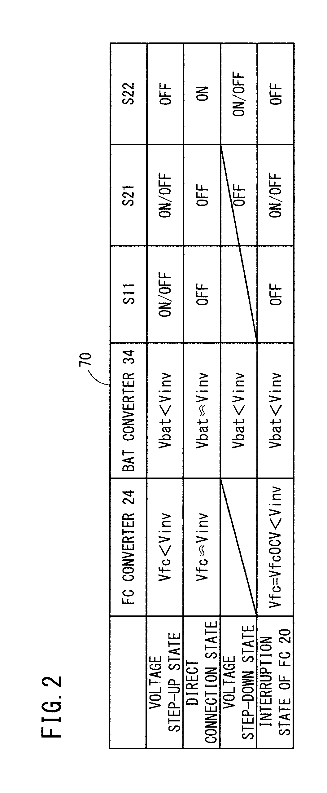
Therefore, it has been found that, even in the case where the fuel cell and the inverter are placed in the direct connection state, the inverter terminal voltage may not be increased to the OCV of the fuel cell.
In a case where the inverter terminal voltage is not increased to the OCV of the fuel cell, in the direct connection state, the fuel cell voltage gets closer to the inverter terminal voltage, and consequently, it may not possible to interrupt electrical power of the fuel cell.
In this case, since the surplus electrical power of the fuel cell is supplied to the electrical storage device through the electrical storage device converter, the electrical storage device converter may be affected adversely, and degradation of the electrical storage device due to overcharging thereof may be caused disadvantageously.

Method used


Image

  • Method of controlling fuel cell system, method of controlling fuel cell automobile, and fuel cell automobile
  • Method of controlling fuel cell system, method of controlling fuel cell automobile, and fuel cell automobile
  • Method of controlling fuel cell system, method of controlling fuel cell automobile, and fuel cell automobile

Examples


first embodiment example

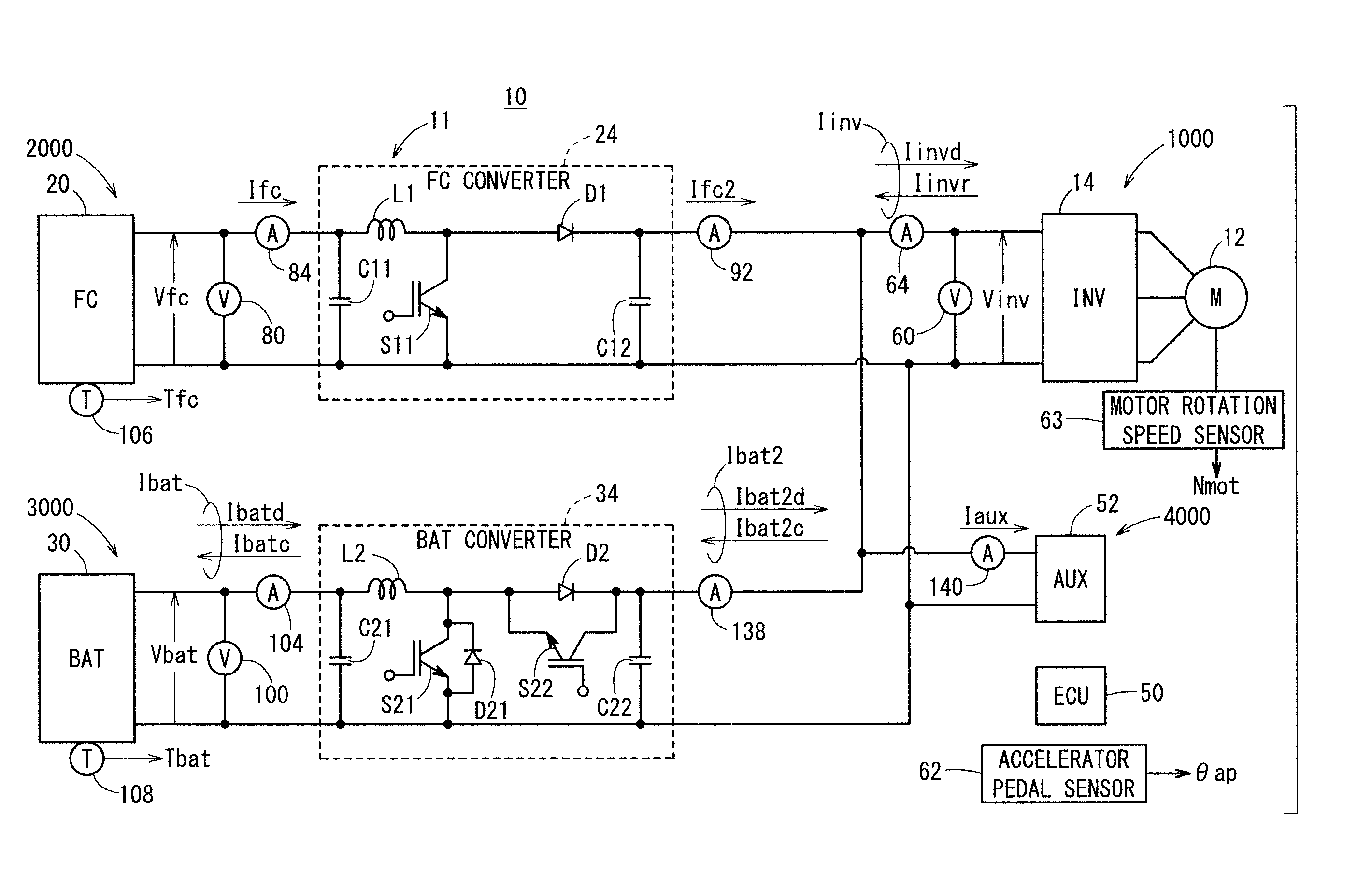
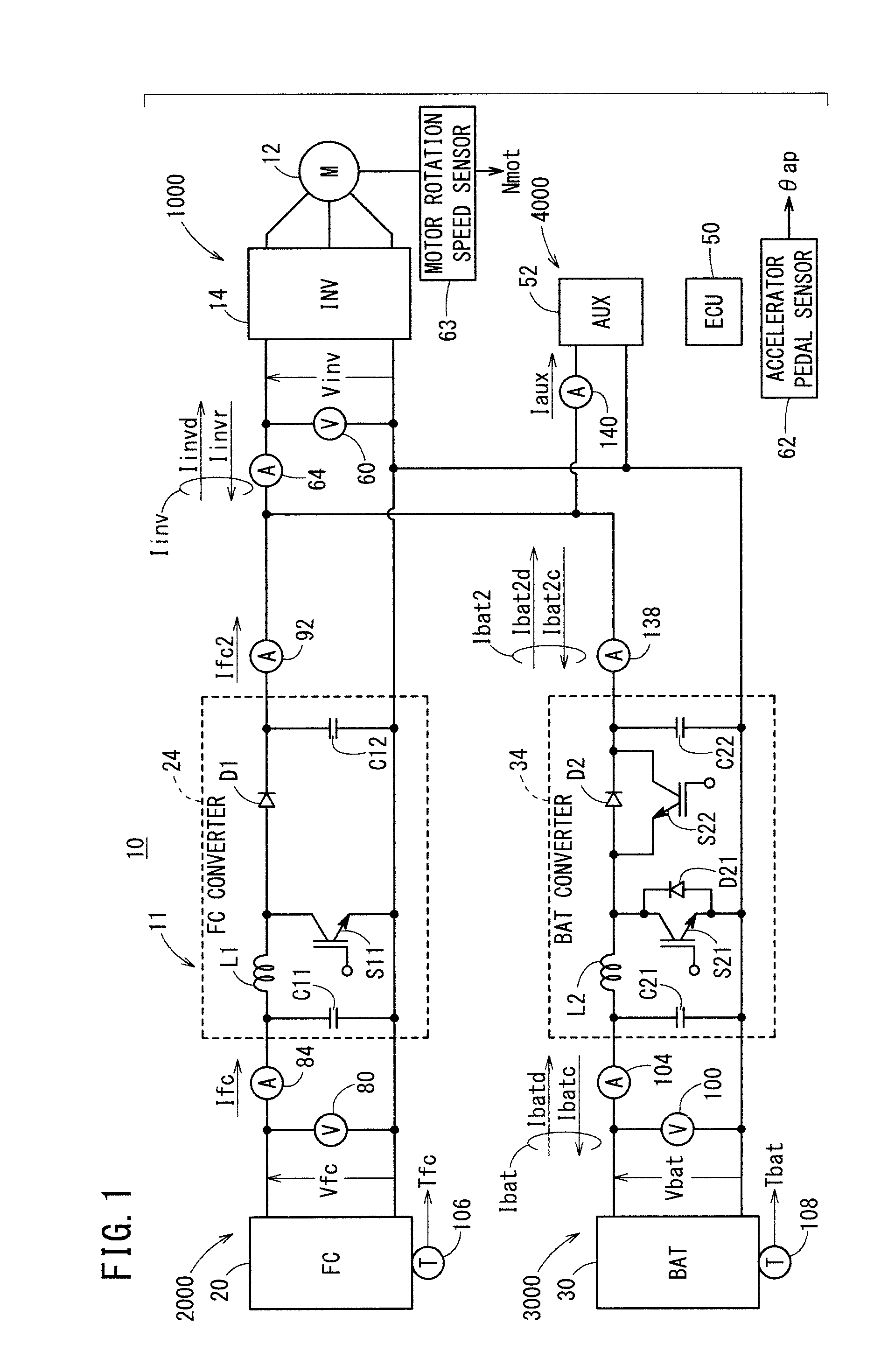
[0082]FIG. 4 is a time chart used for explaining operation of the FC automobile 10 (FIG. 1) for implementing a control method of the first embodiment example.

[0083]FIG. 5 is a flow chart used for explanation of the control method according to the first embodiment example.

[0084]During the period from the time point t0 to the time point t1 (deceleration period, etc.), the system required electrical power Psysreq of the FC automobile 10 is decreased gradually.

[0085]During the period from the time point t1 to the time point t3, the FC automobile 10 is placed in an idling stop state (i.e., a no-idling state or an idle-reduction state) where the value of the vehicle velocity is zero. The system required electrical power Psysreq is kept at a low electrical power in correspondence with the idling stop state.

[0086]During the period from the time point t0 to the time point t2, in order to improve the system efficiency, the BAT converter 34 is controlled to be placed in the direct connection s...

second embodiment example

[0141]FIG. 8 is a time chart used for explaining operation of the FC automobile 10 for carrying out the control method of the second embodiment example.

[0142]During a time period of gradual acceleration of the FC automobile 10 from the time point t20 to the time t21 where the motor required electrical power Pmreq is increased gradually, in order to cover the gradual increase of the motor required electrical power Pmreq, the inverter terminal voltage Vinv (and likewise, the target inverter terminal voltage Vinvtar) is increased gradually, and the target FC electrical power Pfctar is increased gradually as well.

[0143]It should be noted that the gradual increase of the target FC electrical power Pfctar is achieved by the gradual decrease of the target FC voltage Vfctar (i.e., gradual increase of the FC current Ifc).

[0144]In practice, during the period from the time point t20 to the time point t21, the secondary voltage of the BAT converter 34 is set to the target inverter terminal volt...


PUM


Abstract

A method of controlling a fuel cell system, a method of controlling a fuel cell automobile, and a fuel cell automobile are provided. When the SOC of a battery gets closer to an upper limit, there is a risk that overcharging of the battery may occur. In this case, using a BAT converter, inverter terminal voltage is stepped up to FC open circuit voltage or higher, whereby a step-up type FC converter is placed in an interruption state.

Description

CROSS-REFERENCE TO RELATED APPLICATION[0001]This application is based upon and claims the benefit of priority from Japanese Patent Application No. 2015-158275 filed on Aug. 10, 2015, the contents of which are incorporated herein by reference.BACKGROUND OF THE INVENTION[0002]Field of the Invention[0003]The present invention relates to a method of controlling a fuel cell system for driving a load using power sources (fuel cell and electrical storage device) provided in parallel, and a method of controlling a fuel cell automobile in a case where the load is a traction motor, and a fuel cell vehicle for carrying out the above control methods.[0004]Description of the Related Art[0005]In a fuel cell automobile disclosed in Japanese Laid-Open Patent Publication No. 2011-205735 (hereinafter referred to as JP2011-205735A), the fuel cell voltage is stepped up by a fuel cell converter and the electrical storage device voltage is stepped up by an electrical storage device converter. These volta...

Claims


Application Information

Patent Timeline
IPC IPC(8): H01M8/04828B60L11/18
CPCH01M8/04873H01M2250/20B60L11/1883H01M8/04888H01M10/44H01M10/48H01M16/006H01M2220/20Y02P90/40B60L50/72Y02T90/40Y02T10/70Y02E60/50Y02E60/10
Inventor KAZUNO, SHUICHI
Owner HONDA MOTOR CO LTD
Learn More