Systems and methods for stabilization of droplet-plasma interaction via laser energy modulation

a droplet-plasma and laser energy modulation technology, applied in the field of system and method for stabilizing such droplet-plasma interaction systems, can solve the problem of relatively slow approach in comparison to the operation of the system

Active Publication Date: 2017-02-16
ASML NETHERLANDS BV
View PDF4 Cites 5 Cited by
  • Summary
  • Abstract
  • Description
  • Claims
  • Application Information

AI Technical Summary

Benefits of technology

[0010]According to various embodiments, a system comprises: an extreme ultraviolet (EUV) energy detector configured to measure a first amount of EUV energy generated by a first laser pulse impacting a first droplet in a plasma chamber of a laser produced plasma (LPP) EUV system; and, an EUV controller configured to: calculate a first modified laser pulse energy, based on the measured amount of EUV energy generated by the first laser pulse impacting the first droplet in the plasma chamber, and instruct the laser source to deliver a second laser pulse having the calculated first modified energy, thereby altering flight of a second droplet in the plasma chamber; and wherein: the EUV energy detector is further configured to measure a second amount of EUV energy generated by a second laser pulse impacting a second droplet in the plasma chamber of the laser produced plasma (LPP) EUV system; and, the EUV controller is further configured to: calculate a second modified laser pulse energy, based on the measured amount of EUV energy generated by the second laser pulse impacting the second droplet in the plasma chamber; and, instruct the laser source to deliver a third laser pulse having the calculated second modified energy, thereby altering flight of a third droplet in the plasma chamber.

Problems solved by technology

However, this approach is relatively slow in comparison to the operation of the system.

Method used


Image

  • Systems and methods for stabilization of droplet-plasma interaction via laser energy modulation
  • Systems and methods for stabilization of droplet-plasma interaction via laser energy modulation
  • Systems and methods for stabilization of droplet-plasma interaction via laser energy modulation

Examples


Embodiment Construction

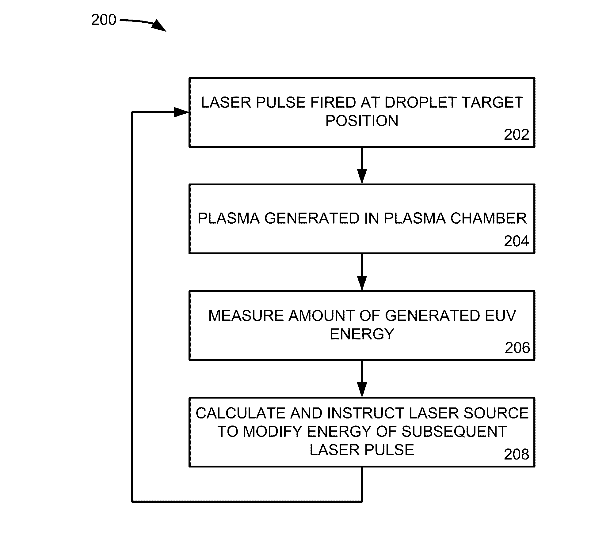
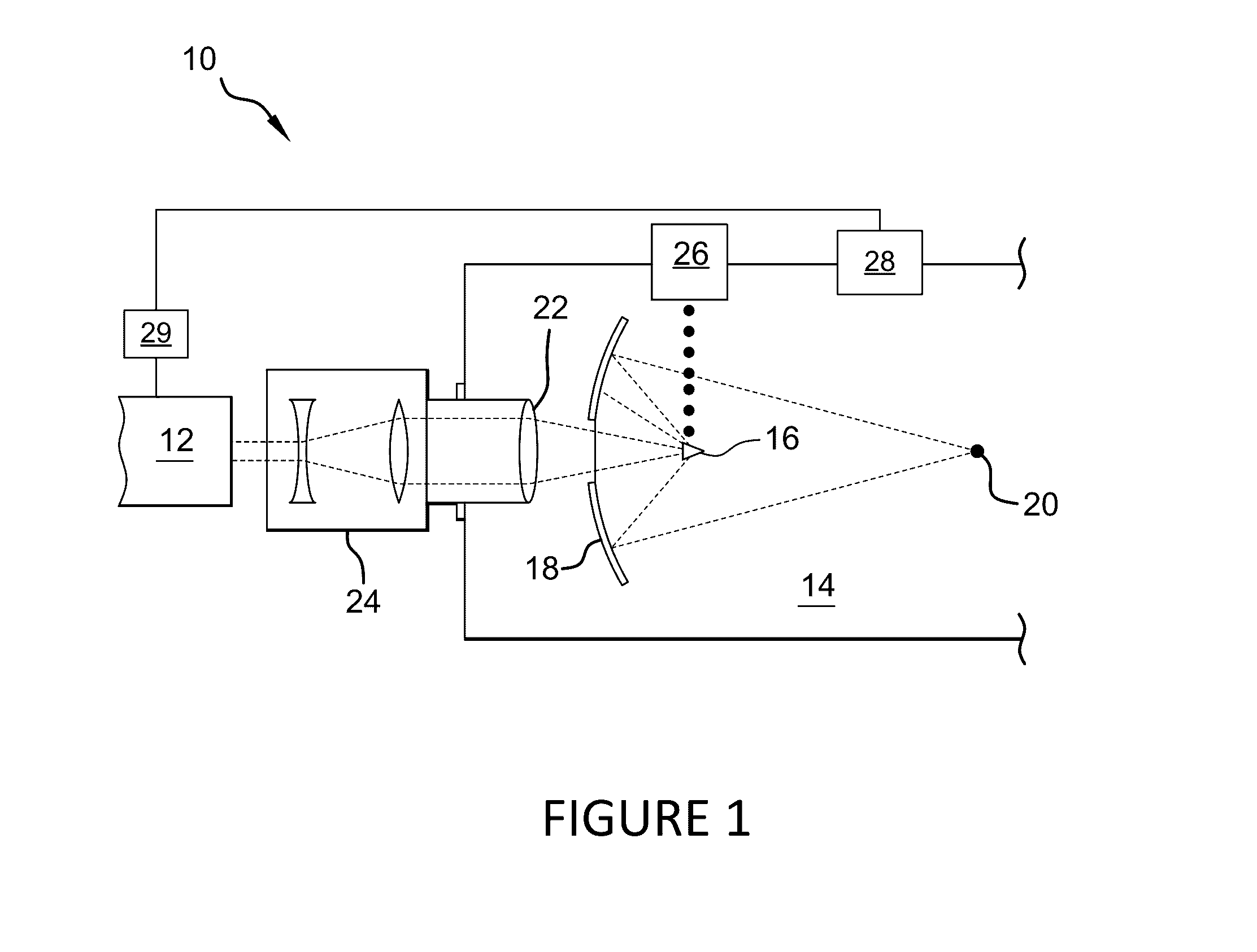
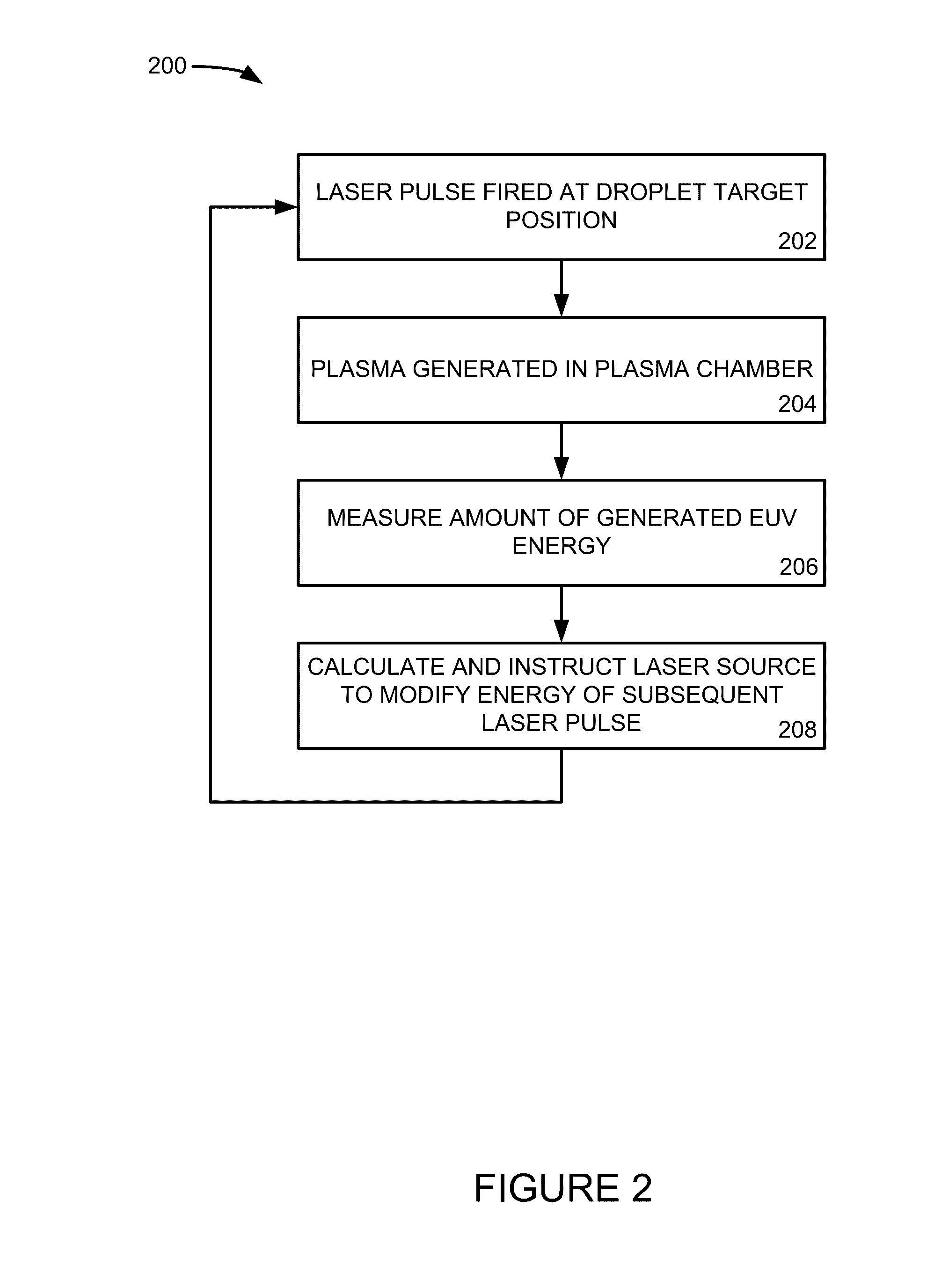
[0015]In LPP EUV systems, a plasma is created when a droplet is impacted by a laser pulse in a plasma chamber. In an idealized model of the LPP EUV system, the created plasma does not affect, or exert any forces on, subsequent incoming droplets. However, in practice, the plasma and the impact of the droplets on the plasma do exert forces on the subsequent incoming droplets in the plasma chamber. The forces can be sonic shockwaves, pressure waves, audio waves, or other types of forces. These forces cause the subsequent droplets to alter their flight by changing speed and / or getting deflected as they approach the plasma being generated. The laser beam then makes less than ideal contact with the subsequent droplets, which further varies the resulting generated plasma and the forces generated therefrom. To counteract these effects in prior approaches, the laser source expends increasing amounts of reserve power to target an ever-widening region in which a target droplet is likely to be ...


PUM


Abstract

In a laser produced plasma (LPP) extreme ultraviolet (EUV) system, a droplet is irradiated by a laser pulse to produce a plasma in a chamber. This generates forces that cause the plasma to destabilize and subsequent droplets to have their flight trajectory and speed altered as they approach the plasma. This destabilization is detectable from oscillations in the amount of EUV energy generated. To reduce the oscillations by stabilizing the plasma and travel of the droplets, a proportional-integral (PI) controller algorithm is used to modify an energy of subsequent laser pulses based on the EUV energy generated in the chamber. By modifying the energy of subsequent laser pulses, the plasma stabilizes, which reduces effects on droplet flight and stabilizes the amount of EUV energy generated, allowing the plasma chamber to operate for longer intervals and to lower the amount of reserve power maintained by a laser source.

Description

BACKGROUND[0001]Field[0002]This non-provisional U.S. patent application relates generally to laser produced plasma (LPP) extreme ultraviolet (EUV) systems and more specifically to systems and methods for stabilization of such LPP EUV systems.[0003]Description of Related Art[0004]The semiconductor industry continues to develop lithographic technologies which are able to print ever-smaller integrated circuit dimensions. Extreme ultraviolet (“EUV”) light (also sometimes referred to as soft x-rays) is generally defined to be electromagnetic radiation having wavelengths of between 10 and 120 nanometers (nm) with shorter wavelengths expected to be used in the future. EUV lithography is currently generally considered to include EUV light at wavelengths in the range of 10-14 nm, and is used to produce extremely small features, for example, sub-32 nm features, in substrates such as silicon wafers. To be commercially useful, it is desirable that these systems be highly reliable and provide co...

Claims


Application Information

Patent Timeline
Patent Type & Authority Applications(United States)
IPC IPC(8): H05G2/00G01J1/42
CPCH05G2/008G01J1/429H05G2/003H05G2/005
Inventor RIGGS, DANIEL JASONRAFAC, ROBERT JAY
Owner ASML NETHERLANDS BV
Why Eureka
Try Eureka