Water control in non-aqueous acid gas recovery systems

Active Publication Date: 2017-02-23
RES TRIANGLE INST
View PDF1 Cites 2 Cited by
  • Summary
  • Abstract
  • Description
  • Claims
  • Application Information

AI Technical Summary

Benefits of technology

The invention described in this patent text has various benefits and options for improvements. Its design is not limited to the specific details provided. The text also mentions that other components, advantages, and modifications of the invention are within the scope of the claims. The goal is to incorporate all relevant publications and patents by reference, indicating each individual one individually.

Problems solved by technology

This represents a significant processing challenge and an operational cost.

Method used


Image

  • Water control in non-aqueous acid gas recovery systems
  • Water control in non-aqueous acid gas recovery systems
  • Water control in non-aqueous acid gas recovery systems

Examples


example 1

5.1. Example 1

Three Phase Equilibrium Measurements to Observe Water Separation in a NAS CO2 Removal System

[0052]A 5 mL sample of an exemplary NAS consisting of equimolar portions of 2-fluorophenethylamine (2FPEA) and octafluoropentanol (OFP) and a 5 mL aliquot of DI water were placed in a stirred glass, round bottom flask equipped with an overhead condenser. Excess water was maintained in the vessel at all times to ensure that equilibrium H2O loading in the NAS was achieved. The pressure of the stirred vessel was maintained at atmospheric pressure. The two phase sample was heated to the desired temperature, i.e., 40, 80, or 90° C., using a electric heater jacket and 100 mL / min of a CO2—N2 blend gas with various compositions was bubbled through the two phase liquid sample. The CO2—N2 feed was stopped once the CO2 concentration in the outlet stream was >99% of the inlet concentration. A 0.9 mL sample from the NAS phase was extracted from the batch vessel using a syringe through a sept...

example 2

5.2. Example 2

Water Balance in a NAS CO2 Removal Process

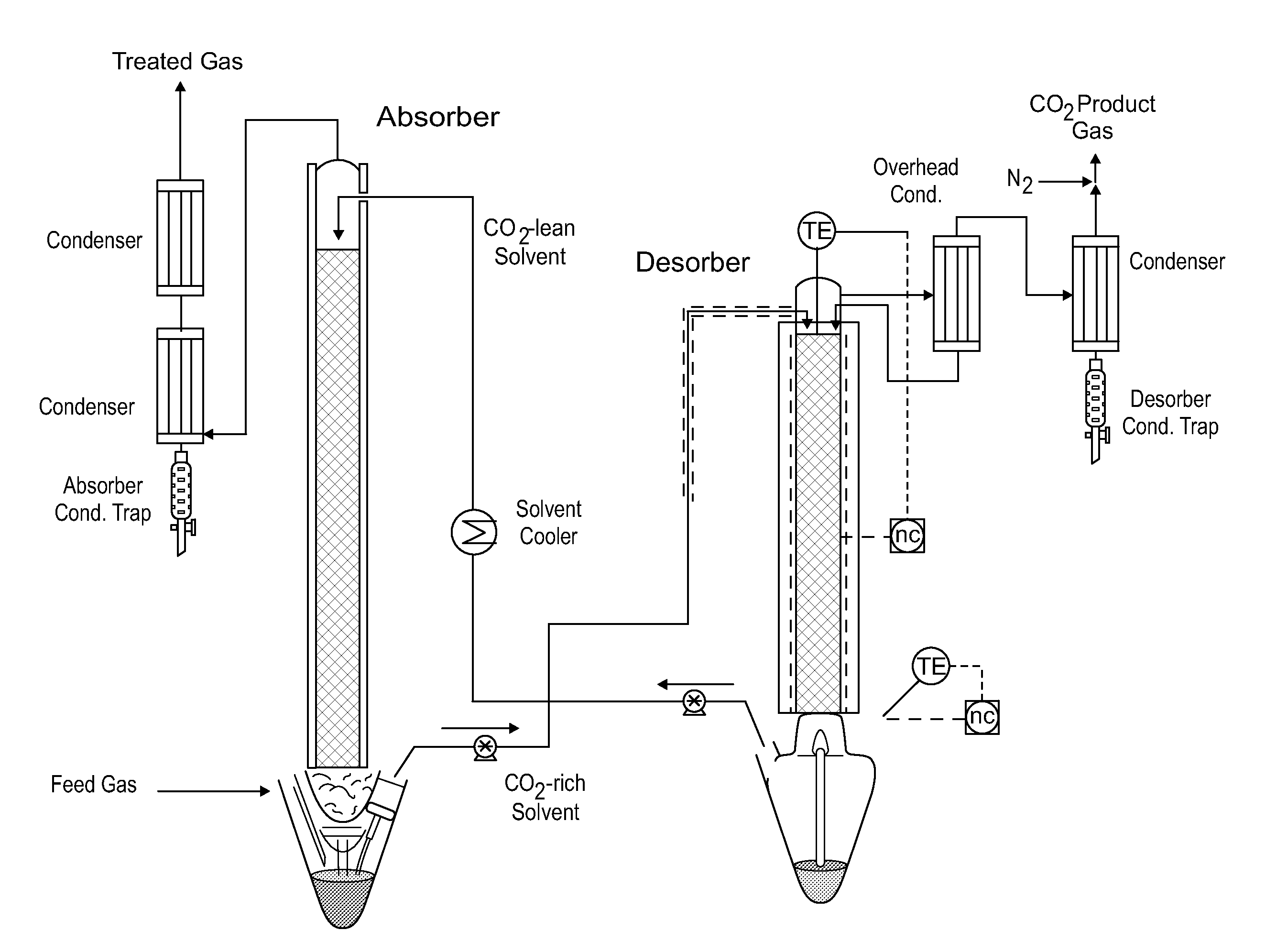
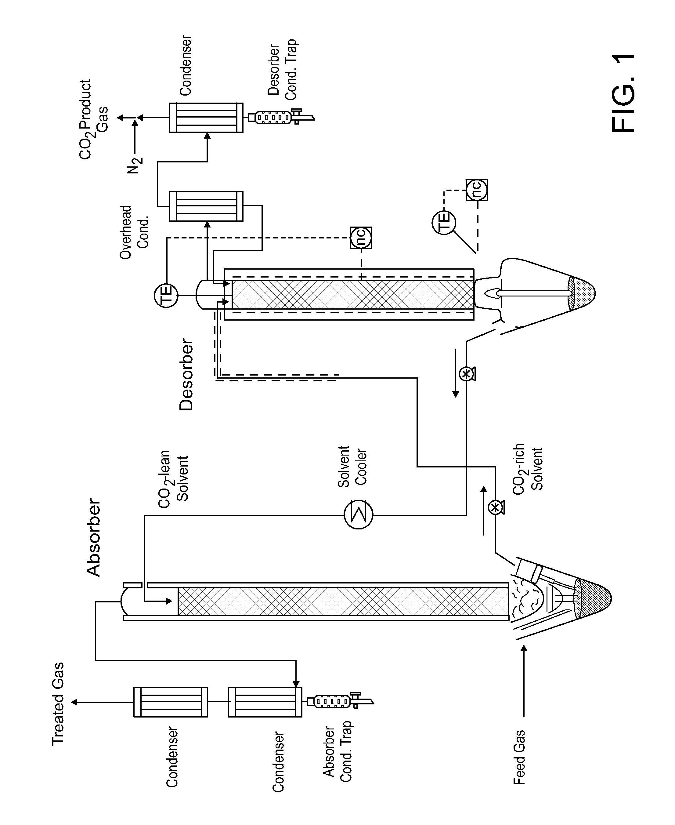
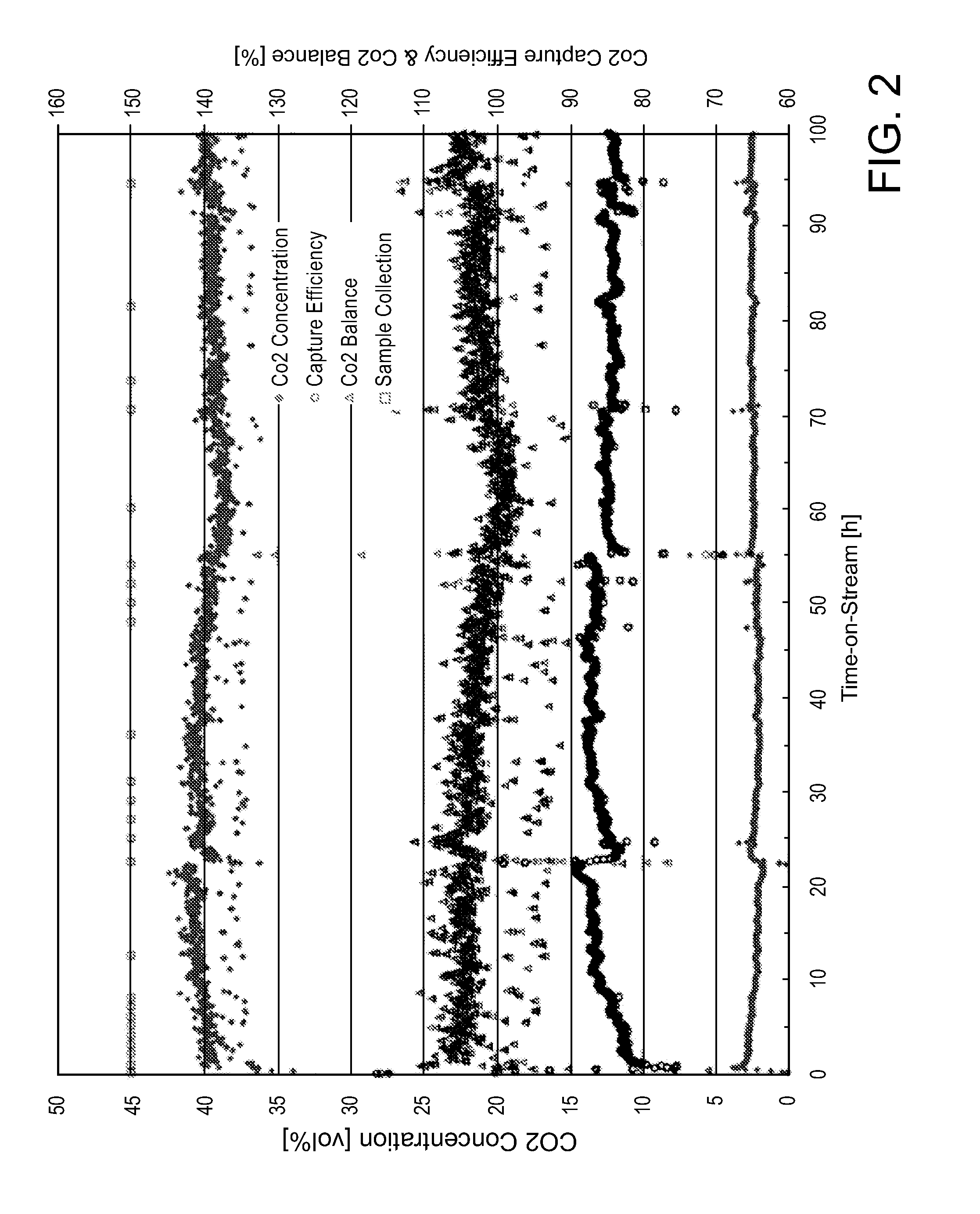
[0070]An experiment was performed in a lab-scale, continuous flow gas absorption system having a standard absorber-desorber configuration to experimentally demonstrate control of the water balance in a NAS CO2 removal process. A simplified schematic of the LsGAS is provided in FIG. 1 and the operating conditions are provided in Table 3. An exemplary NAS consisting of equimolar portions of 2-fluorophenethylamine (2FPEA) and octafluoropentanol (OFP) was used in this study. Selected process measurements from this experiment are presented in FIG. 2. Under these conditions the system was found to be very stable over the entire 100 h experiment exhibiting a CO2 capture efficiency of ˜85% and a CO2 balance of ˜102%±2%.

TABLE 3Feed GasFlow Rate3 SLPMComposition13.3% CO2, 5.65%H2O (sat @ 35° C.),Bal. N2Temperature40° C.AbsorberFlow Rate23 g / minInlet Temp.40° C.Pressure1 atmDesorberTemp.90° C.Pressure1 atm

[0071]Results presented in FIG. 2...

example 3

5.3 Example 3

Controlling the Water Balance in a NAS CO2 Removal Process (Study #1)

[0079]An experiment was performed to demonstrate that the formation of a water-rich phase can be avoided in the process through control of the operating conditions of the CO2 absorber thus eliminating the necessity for a water-NAS separation device and creating a single phase NAS process. Specifically, operating the process such that water-rich stream containing trace quantities of NAS is eliminated.

[0080]A simplified schematic of the LsGAS is provided in FIG. 1 and the operating conditions are provided in Table 3. An exemplary NAS consisting of equimolar portions of 2-fluorophenethylamine (2FPEA) and octafluoropentanol (OFP) was used in this study. For the treated gas to carry the same mass of water it must leave the absorber slightly warmer than the flue gas enters the column since both gases are approximately saturated with water and the flow rate of the treated gas is lower than the feed gas due to...


PUM

PropertyMeasurementUnit
Massaaaaaaaaaa
Massaaaaaaaaaa
Pressureaaaaaaaaaa

Abstract

This invention is directed to methods and systems for controlling water in acid gas removal processes comprising the steps of a) treating the gas stream in an absorption zone with the NAS absorption liquid; b) direction the acid gas-loaded NAS absorption liquid to a regeneration zone; c) directing the regenerated NAS absorption liquid to step a); and d) controlling the first and second set of conditions.

Description

CROSS REFERENCE TO RELATED APPLICATIONS[0001]This application claims the benefit of 61 / 939,569 filed Feb. 13, 2014, Coleman et al., Atty. Docket No. RTI13004USV which is hereby incorporated by reference in its entirety.STATEMENT REGARDING FEDERALLY SPONSORED RESEARCH OR DEVELOPMENT[0002]This invention was made with government support under Grant No. DE-AR0000093 awarded by the U.S. Department of Energy. The government has certain rights in the invention.FIELD OF THE INVENTION[0003]This invention relates generally to the discovery of methods and systems for controlling water in acid gas (AG) removal processes.BACKGROUND OF THE INVENTION[0004]2.1. Introduction[0005]Greenhouse gas and acid gas (AG) emissions (CO2, SOx, NOx, H2S, COS, CS2) from power generation or other industrial processes are a huge problem globally. Many different approaches are being explored to recover such gases from combustion or other sources. The significant reduction of carbon dioxide (CO2) emissions from exis...

Claims


Application Information

Patent Timeline
IPC IPC(8): B01D53/14
CPCB01D53/1412B01D53/1425B01D53/1493B01D53/1475B01D2252/202B01D2252/20426B01D2252/2028B01D2252/20405B01D2252/40B01D2252/20421B01D2252/2026B01D2252/204B01D2252/30B01D2258/0233B01D2258/0283Y02C20/40
Inventor COLEMAN, LUKELAIL, MARTYAMATO, KELLY E.TANTHANA, JAK
Owner RES TRIANGLE INST
Why Eureka
Try Eureka