Supercharge Your Innovation With Domain-Expert AI Agents!

Cupper draw pad

Active Publication Date: 2017-02-23
ANHEUSER-BUSCH
View PDF15 Cites 2 Cited by
  • Summary
  • Abstract
  • Description
  • Claims
  • Application Information

AI Technical Summary

Benefits of technology

The present disclosure is about a draw pad for a cupping press that reduces earing when clamping and punching metal blanks during a drawing process. The draw pad has inner and clamping surfaces with specifically located relief areas that evenly distribute gripping forces, and prevent ears from being formed during the process. This results in a cup-shaped body with reduced earing, which does not interfere with subsequent forming operations such as making the cup-shaped body into a metal can or bottle-shaped container. The technical advantage of the disclosed embodiments is the improved quality of the cup-shaped body with reduced earing.

Problems solved by technology

The problem of earing is attributable to the drawing process, and the anisotropy of a blank of sheet metal is the predominate cause of earing.
At that time, all the clamping forces concentrate on those ears and can cause them to become pinched or thinned.
Earing is problematic in that it may cause material to be wasted, such as when the earing portion of the drawn cup needs to be cut away, or it may lead to undesirable metal portions that may disrupt downstream formation processes.
Non-round blanks, however, often have less material available approximately forty-five degrees to the material grain, i.e., the direction the sheet metal was rolled, and require more complex and expensive tooling in the cupping press and in downstream manufacturing processes.

Method used


Image

  • Cupper draw pad
  • Cupper draw pad
  • Cupper draw pad

Examples


Embodiment Construction

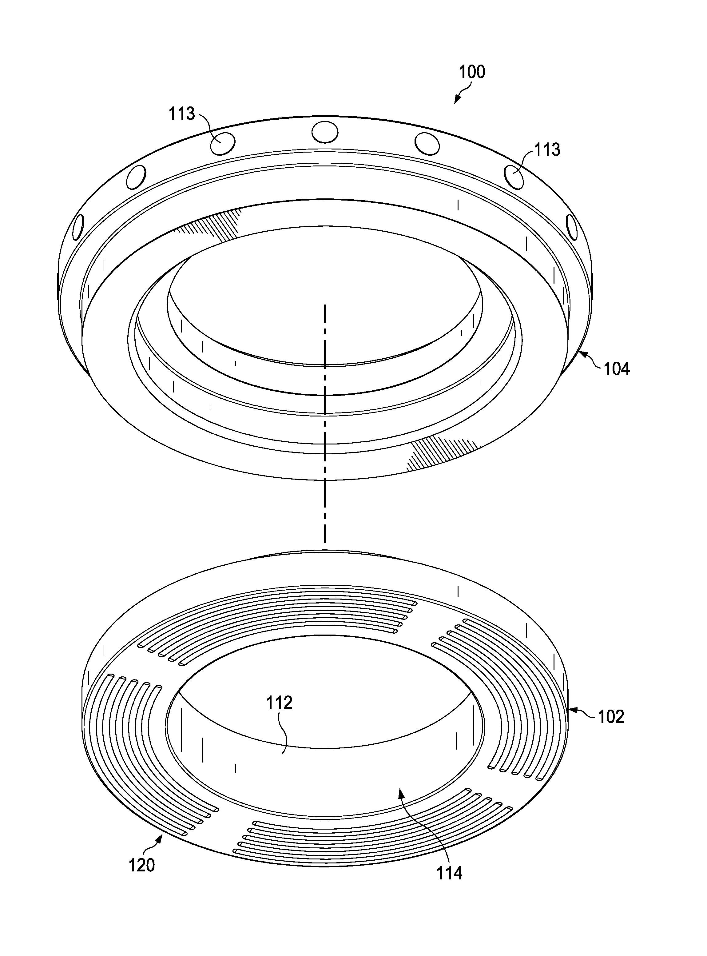
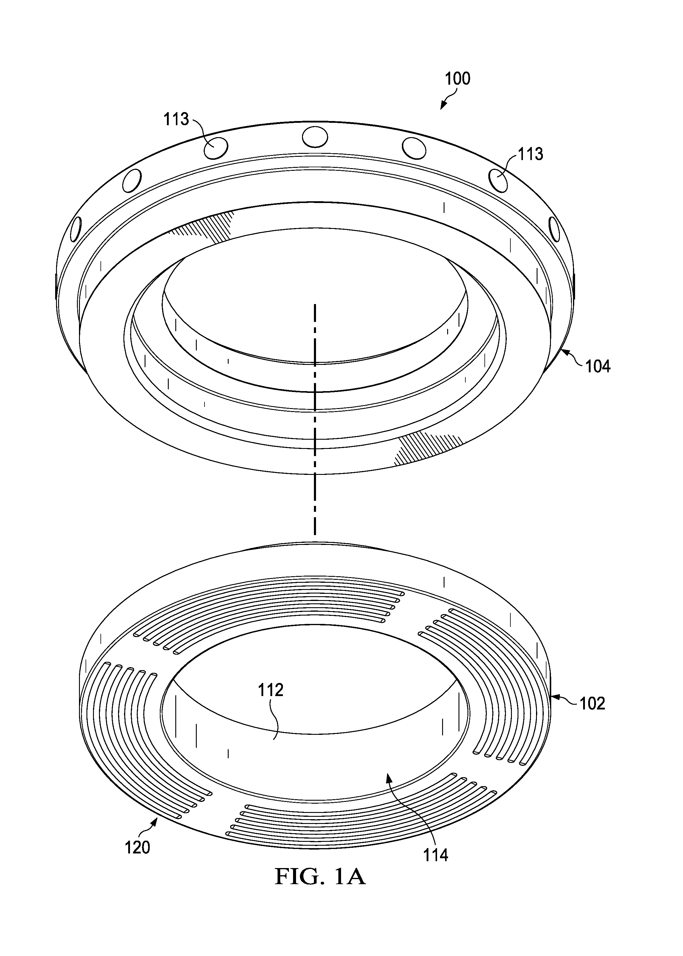
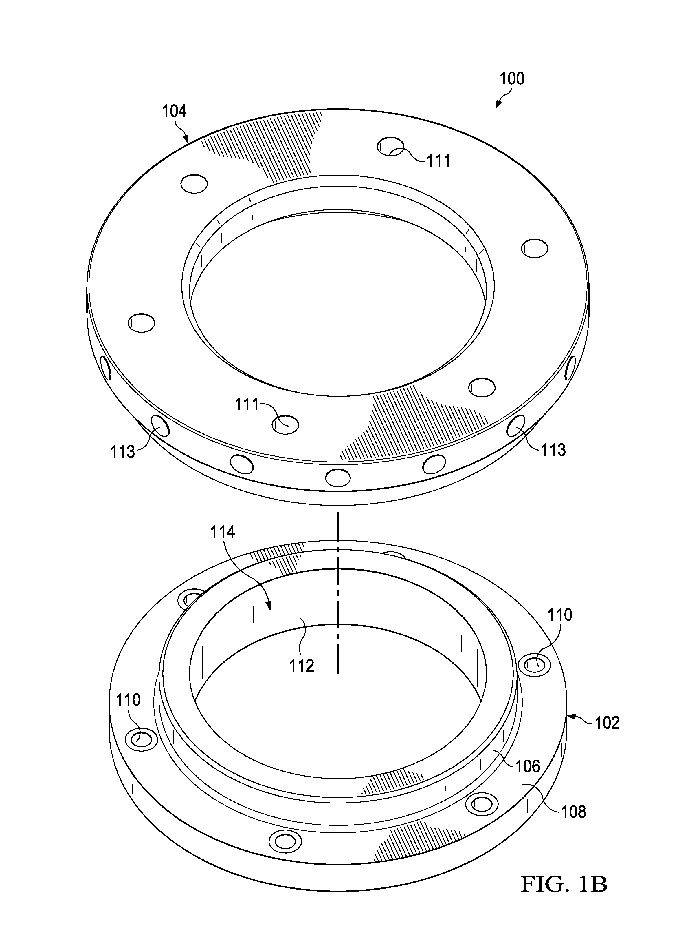
[0021]FIGS. 1A and 1B illustrate exploded, isometric views of a draw pad assembly 100, where FIG. 1A is a view toward a clamping surface 120, and FIG. 1B is a view in a direction opposite the view direction of FIG. 1A. The draw pad assembly 100 is part of a die assembly used in a drawing process. The draw pad assembly 100 includes a draw pad 102 and a casing 104. The draw pad 102 is formed of an ultra-hard material such as carbide, and the casing 104 is formed of a softer material. According to one embodiment, the draw pad 102 is formed of a carbide material with a nickel binder, and the casing 104 is formed of tool steel. When a cup is formed, a metal sheet is clamped between the draw pad 102 and a blank-and-draw die to allow a punch to form the metal into a cup-like part as it forces the metal into a die cavity and the metal flows between the punch and the blank-and-draw die. The machine that includes the punch, the draw pad 102, the casing 104, and the blank-and-draw die is often...


PUM

PropertyMeasurementUnit
Angleaaaaaaaaaa
Angleaaaaaaaaaa
Angleaaaaaaaaaa

Abstract

A draw pad reduces instances and the extent of earing when a blank of metal is clamped and punched during a drawing process that results in the formation a cup-shaped body from the blank. A draw pad for a cupping press includes an inner surface that defines a draw aperture that is configured to receive a punch. The draw pad also includes a clamping surface that has a first force concentrating segment disposed circumferentially spaced apart from a second force concentrating segment, where each force concentrating segment includes a first arcuate groove and a second arcuate groove that is disposed concentric and radially spaced apart from the first arcuate groove.

Description

CROSS REFERENCE TO RELATED APPLICATIONS[0001]This application claims priority to U.S. Provisional Application for Patent Ser. No. 62 / 207,722, filed Aug. 20, 2015, which is hereby incorporated by reference.TECHNICAL FIELD[0002]This disclosure relates to a tool for use in manufacturing metal containers, and in particular, to a cupper draw pad that reduces earing during a drawing process.[0003]Background of the Disclosure[0004]Thin-walled, two-piece metal containers are often produced using drawing processes. In a drawing process, a flat circular blank of sheet metal, for example aluminum, is drawn through one or more drawing dies to form a shallow preform cup. The blank of sheet metal used to form the preform cup has a particular anisotropy, which is the directional variation of sheet metal's mechanical properties. In other words, the blank of sheet metal will react differently to stresses applied in one direction than it would to the same stresses applied in a different direction.[00...

Claims


Application Information

Patent Timeline
IPC IPC(8): B21D51/26B21D22/20
CPCB21D22/20B21D51/26B21D22/22B21D22/28B21D24/04
Inventor SCHREMMER, MARKSCHAEFER, SCOTTWAGNER, MARK
Owner ANHEUSER-BUSCH
Features
  • R&D
  • Intellectual Property
  • Life Sciences
  • Materials
  • Tech Scout
  • Unparalleled Data Quality
  • Higher Quality Content
  • 60% Fewer Hallucinations
Learn More