
Gas supply device, hydrogen station, and gas supply method

a gas supply device and hydrogen station technology, applied in the direction of electrochemical generators, container discharging methods, container filling under pressure, etc., can solve the problem that the hydrogen filling in a vehicle cannot be quickly resumed, and achieve the effect of suppressing the gas pressur

Active Publication Date: 2017-02-23
KOBE STEEL LTD
View PDF12 Cites 10 Cited by
  • Summary
  • Abstract
  • Description
  • Claims
  • Application Information

AI Technical Summary

Benefits of technology

The technical effect of this patent is to prevent the pressure in an accumulator from decreasing.

Problems solved by technology

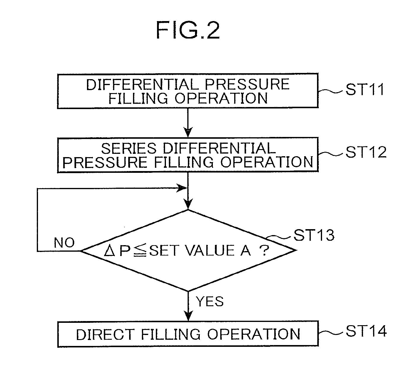
There are the following problems in the configuration for performing the storing operation after the differential pressure filling operation to recover the gas pressure in the accumulator.
Hydrogen filling in a vehicle cannot be quickly resumed.

Method used


Image

  • Gas supply device, hydrogen station, and gas supply method
  • Gas supply device, hydrogen station, and gas supply method
  • Gas supply device, hydrogen station, and gas supply method

Examples


Embodiment Construction

[0012]A mode for carrying out the present invention is explained in detail below with reference to the drawings.

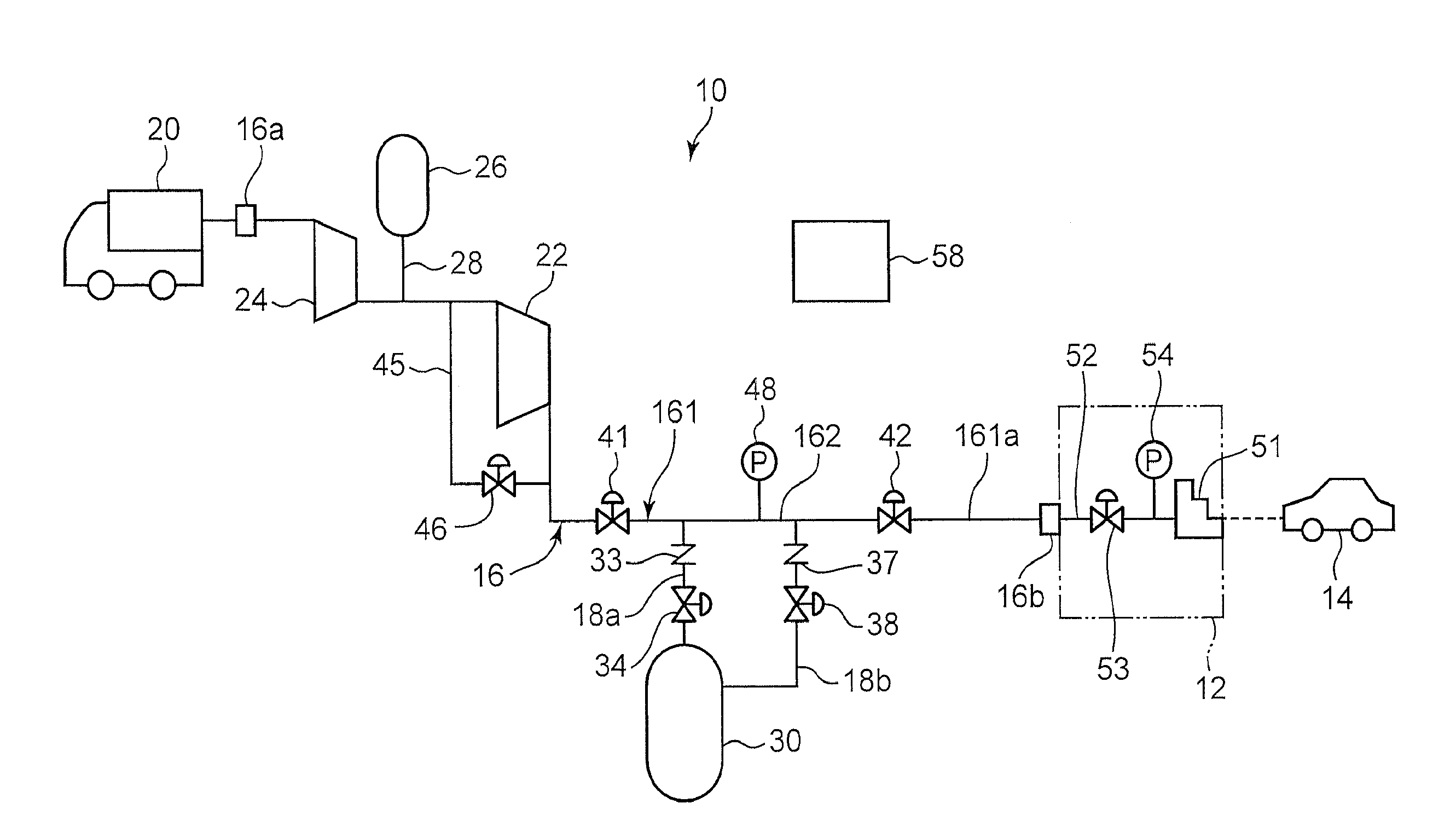
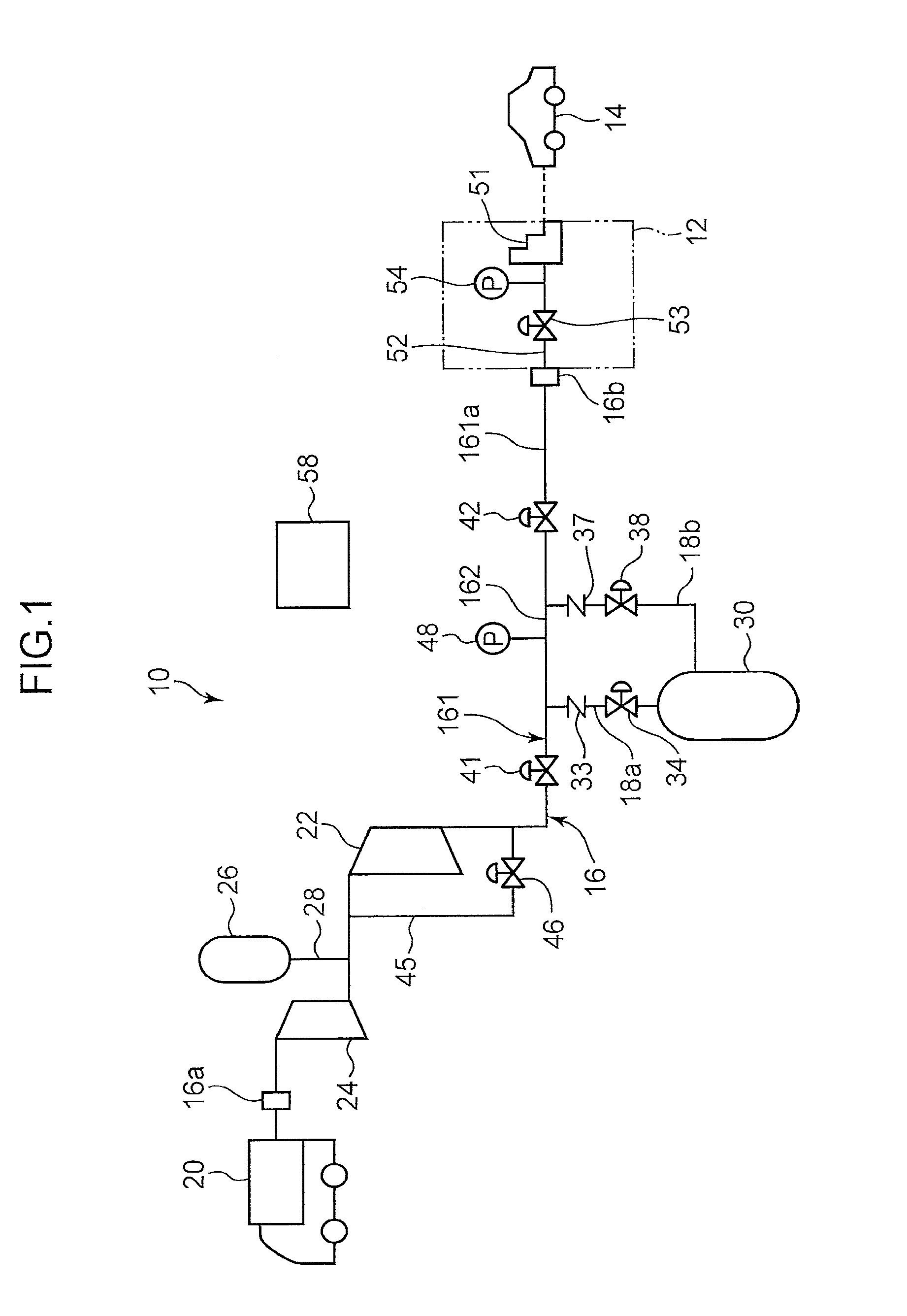
[0013]As shown in FIG. 1, a gas supply device 10 according to this embodiment is provided in, for example, a hydrogen station functioning as a fueling stand of hydrogen gas. According to a filling command from a dispenser 12, which is filling equipment, the gas supply device 10 supplies the hydrogen gas to the dispenser 12 side. That is, the hydrogen station includes the gas supply device 10 and the dispenser 12 connected to an outflow end of the gas supply device 10. The dispenser 12 fills the hydrogen gas in a tank provided in a vehicle 14 (a tank mounting device). The vehicle 14 is, for example, a fuel-cell vehicle.

[0014]The gas supply device 10 includes a first compressor 22, a second compressor 24, a storage tank 26, an accumulator 30, a gas flow passage 16, and a controller 58 (a control device). The gas flow passage 16 includes a main channel 161 and a short-circuit...


PUM


Abstract

A gas supply device includes a first compressor that compresses hydrogen gas, an accumulator disposed downstream of the first compressor and supplying the hydrogen gas to a dispenser that fills the hydrogen gas in a vehicle, and a gas flow passage that connects the first compressor, the accumulator, and the dispenser, and a control device. The gas flow passage includes a lead-in line for leading the hydrogen gas into the accumulator, a lead-out line for leading out the hydrogen gas from the accumulator, a lead-in side valve, and a lead-out side valve. The control device is capable of simultaneously bringing the lead-in side valve and the lead-out side valve into an open state.

Description

TECHNICAL FIELD[0001]The present invention relates to a gas supply device, a hydrogen station, and a gas supply method.BACKGROUND ART[0002]There has been known a gas supply device that temporarily stores gas supplied from a hydrogen producing device and supplies the stored gas to a gas dispenser as disclosed in Patent Literature 1 described below. Specifically, in the gas supply device of this type, a hydrogen compressor and an accumulator are provided in a pipe. The gas led in from the hydrogen producing device is compressed by the hydrogen compressor, and the gas compressed by the hydrogen compressor is stored in the accumulator. The gas stored in the accumulator is supplied to the dispenser according to a pressure difference between a gas pressure in the accumulator and a gas pressure on the dispenser side (differential pressure filling operation). Therefore, during the differential pressure filling operation, the gas pressure in the accumulator gradually drops. If the gas pressu...

Claims


Application Information

Patent Timeline
IPC IPC(8): F17C5/06
CPCF17C5/06F17C2205/0326F17C2221/012F17C2223/0123F17C2225/0123F17C2223/036F17C2270/0178F17C2227/0164F17C2227/0185F17C2250/01F17C2260/025F17C2265/063F17C2265/065F17C2225/036F17C2270/0184Y02P90/45Y02E60/32F17C13/04
Inventor NAGURA, KENJITAKAGI, HITOSHIUBA, TAKURO
Owner KOBE STEEL LTD
Learn More