
Air cleaning device using water as filter

a technology of air cleaning device and water filter, which is applied in the direction of dispersed particle separation, transportation and packaging, and separation processes, etc., can solve the problems of raising household expenditure, unable to solve the problem, and common air cleaners cannot solve the problem, so as to improve the safety of the environment

Inactive Publication Date: 2017-03-02
TSAI TSUNG HSIN +1
View PDF4 Cites 3 Cited by
  • Summary
  • Abstract
  • Description
  • Claims
  • Application Information

AI Technical Summary

Benefits of technology

The present invention is an air cleaning device that uses water as a filter. The device pumps water into multiple pipes to suck air from a tank through multiple air inlets and filter it. This allows for fast cleaning of a wide area of air, while also achieving effective convection and high replacement of air.

Problems solved by technology

However, the filters cannot completely filter very tiny particles suspended in the air.
Therefore, a common air cleaner cannot solve but can only soothe the problem of allergy.
Besides, filters need replacing frequently to maintain the highest efficiency of the air cleaner, which would raise household expenditure.
Further, dirt and particles are likely to adhere to filters and blades, which may cause noise, impair air suction, and increase power consumption.
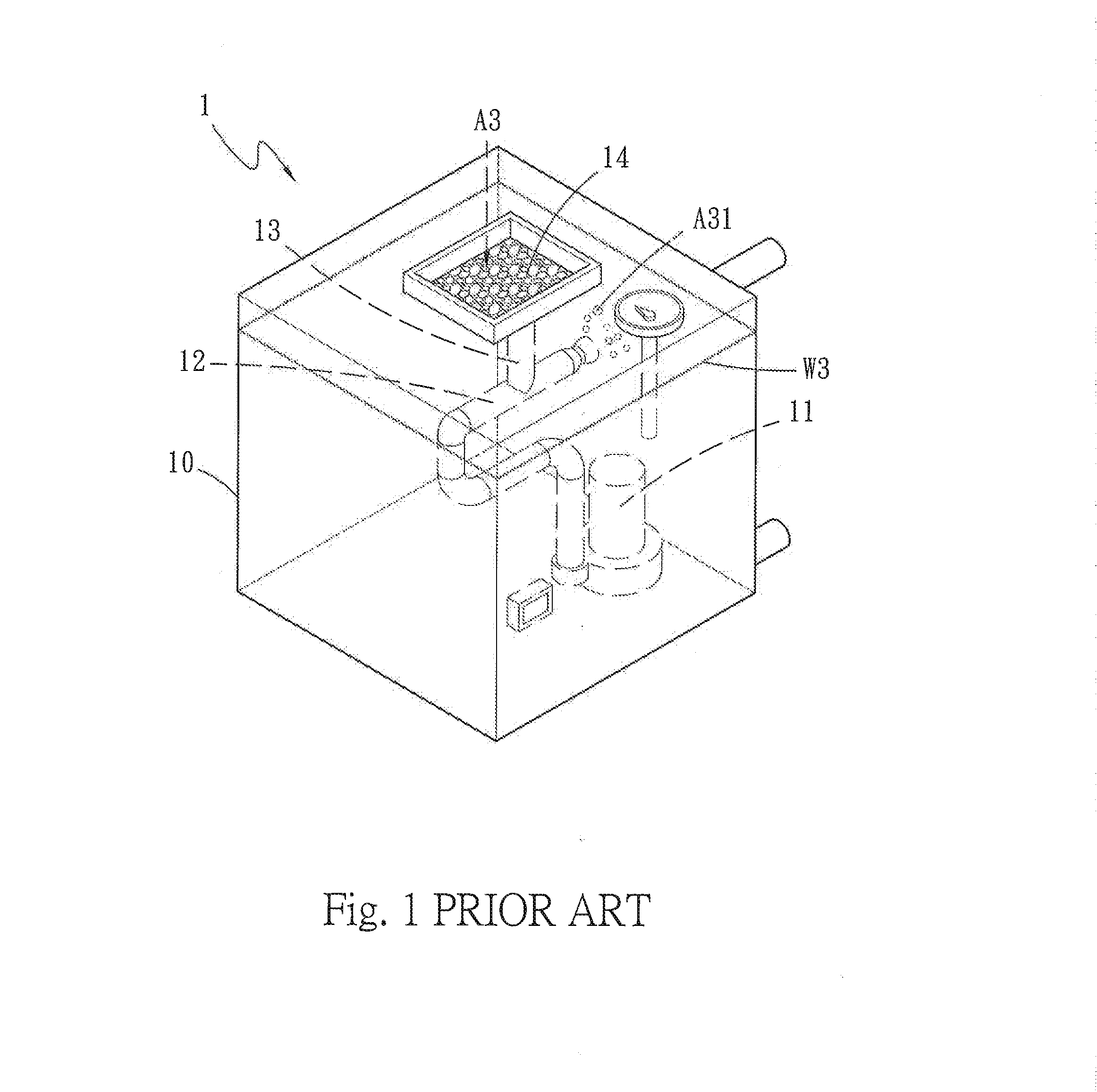
However, the prior art has a problem: clean air A31 cannot be exhausted from the water tank 10 but is persistently accumulated in the water tank 10.
Thus, the air-water mixing and air cleaning function of the air cleaning device is disabled.
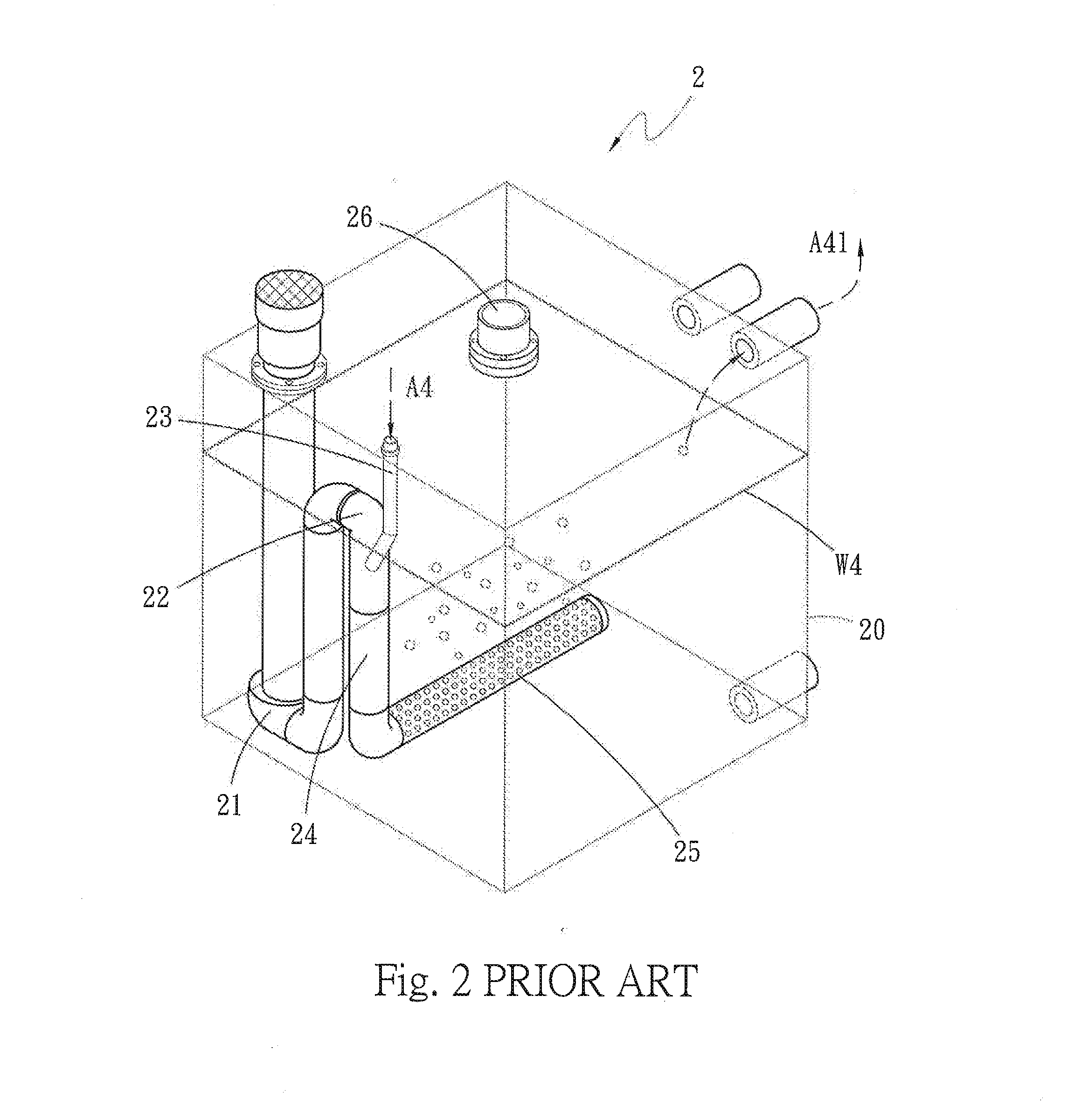
However, there are two factors impairing household application of the prior art: only a single set of the venturi tube-based vacuum sucker 23 is hard to suck sufficient waste gas A4 for effectively purifying the waste gas A4; the absorbing liquid W4 of the gas cleaning tower needs manually replacing frequently.

Method used


Image

  • Air cleaning device using water as filter
  • Air cleaning device using water as filter
  • Air cleaning device using water as filter

Examples


Embodiment Construction

[0025]Below, embodiments are described in detail in cooperation with attached drawings to make easily understand the objectives, technical contents, characteristics and accomplishments of the present invention. Before the detailed description of the present invention, it should be noted: like elements are denoted by like numerals thereinafter.

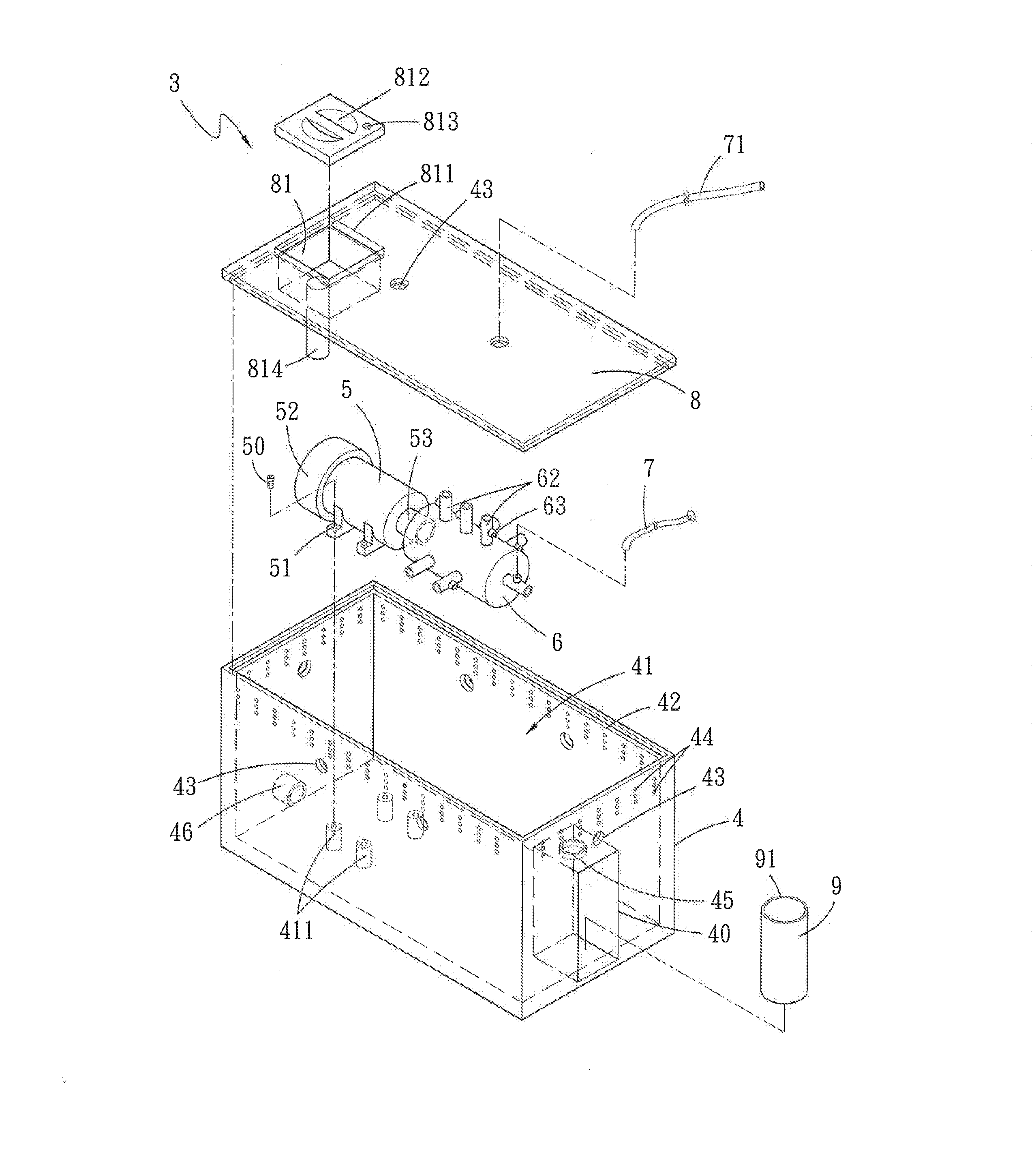
[0026]Refer to FIG. 3 and FIG. 4. The air cleaning device 3 using water as a filter of the present invention comprises a water tank 4, a water pump 5, a pressure equalizer 6, a plurality of air-inhale tubes 7, at least one extension tube 71, a cover 8, and an overflow container 9.

[0027]The water tank 4 has an accommodation space 41 for containing water W1. A plurality of supports 411 protrude from the bottom of the accommodation space 41. The top of the accommodation space 41 of the water tank 4 has an opening 42. The upper region of the water tank 4 has a plurality of air inlets 43 and a plurality of air outlets 44, which interconnect with the...


PUM


Abstract

An air cleaning device using water as a filter comprises a water tank, a water pump, a pressure equalizer and air-inhale tubes. The water tank includes an accommodation space for containing water, air inlets and air outlets. A cover hoods the water tank and has a water storage tank and air inlets. The water pump is disposed inside the water tank and connected with the pressure equalizer. Jet pipes of the pressure equalizer respectively interconnect with the air inlets through the air-inhale tubes. The water pump sucks the water in the accommodation space. Through the air-inhale tubes, the jet pipes inhale air in a jet fashion from exterior of the air inlets disposed in multiple directions. The air cleaning device can filter out the impurities in the air and fast clean the air of a large space. The present invention uses water as the filter and favors environmental protection.

Description

FIELD OF THE INVENTION[0001]The present invention relates to an air cleaning device, particularly to an air cleaning device using water as a filter.BACKGROUND OF THE INVENTION[0002]In an investigation of the Environmental Protection Administration, it is found that household (indoor) air pollution is higher than outdoor air pollution by several times to tens of times. Air pollution is likely to cause pulmonary allergy or asthma. Therefore, many families purchase air cleaners to improve the quality of indoor air.[0003]A common air cleaner uses an electric fan to suck and exhaust air, wherein several filters are arranged before the electric fan, and wherein the blades of the electric fan are driven by a motor to rotate at a high speed to suck air into the air cleaner, whereby the particles suspended in the air is filtered out by the filters. However, the filters cannot completely filter very tiny particles suspended in the air. Therefore, a common air cleaner cannot solve but can only...

Claims


Application Information

Patent Timeline
IPC IPC(8): B01D53/18B01F3/04B01D53/14
CPCB01D53/185B01D2252/103B01F3/04B01D53/1493B01D53/79B01D47/021B01D53/72B01D2257/502B01D2257/504B01D2257/80B01D2257/90B01D2257/91B01D2258/06B01D2259/4508B01D2259/455
Inventor TSAI, TSUNG-HSINTSAI, I-TA
Owner TSAI TSUNG HSIN
Learn More