Safety system for industrial robot

a safety system and industrial robot technology, applied in the field of robot safety systems, can solve the problems of difficult to estimate the frictional torque with a high precision, important safety issues remain unsolved, and the programming of robots used in the industry requires specialized knowledg

Active Publication Date: 2017-03-02
UNIVERSAL ROBOT
View PDF9 Cites 30 Cited by
  • Summary
  • Abstract
  • Description
  • Claims
  • Application Information

AI Technical Summary

Benefits of technology

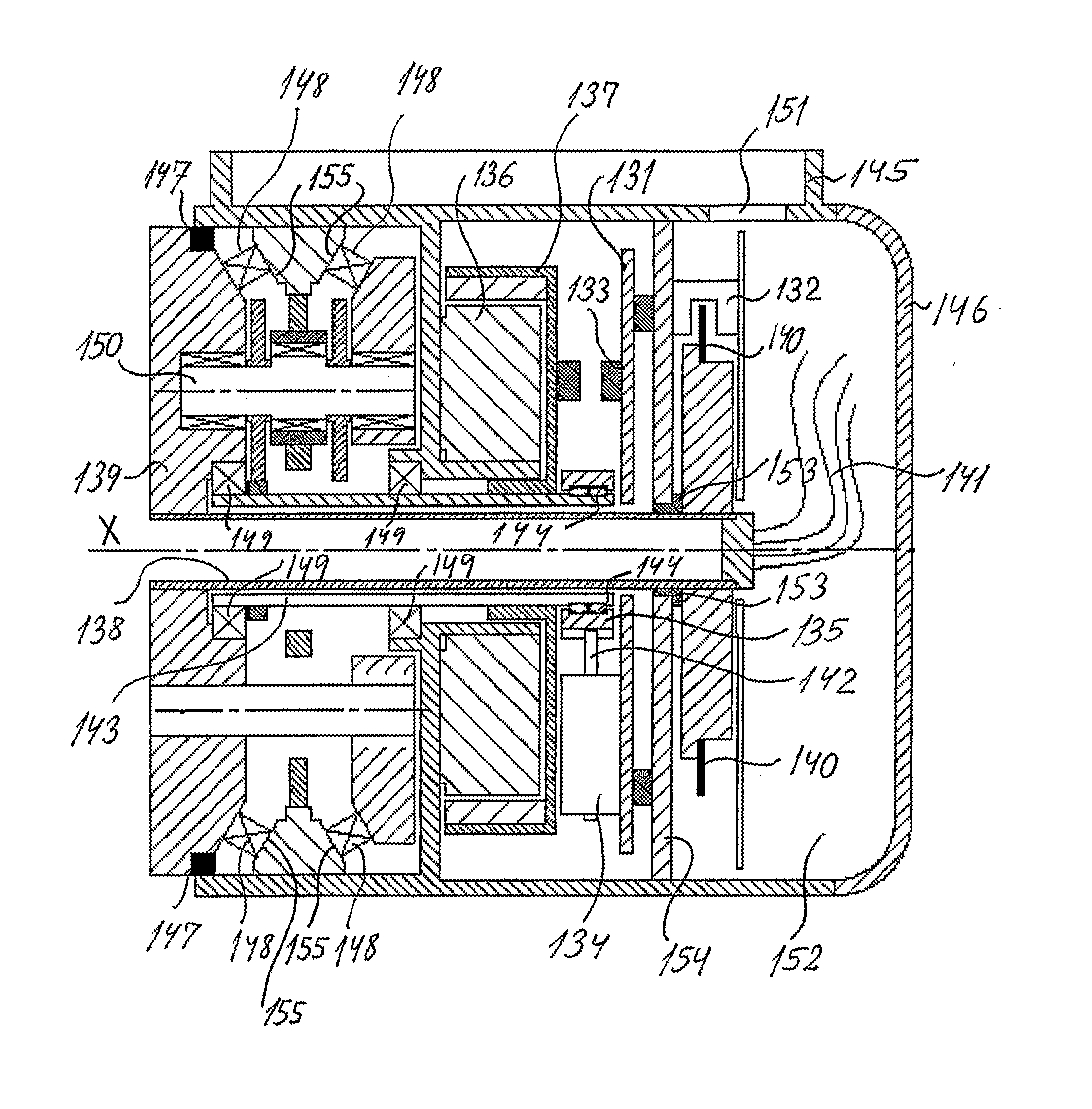
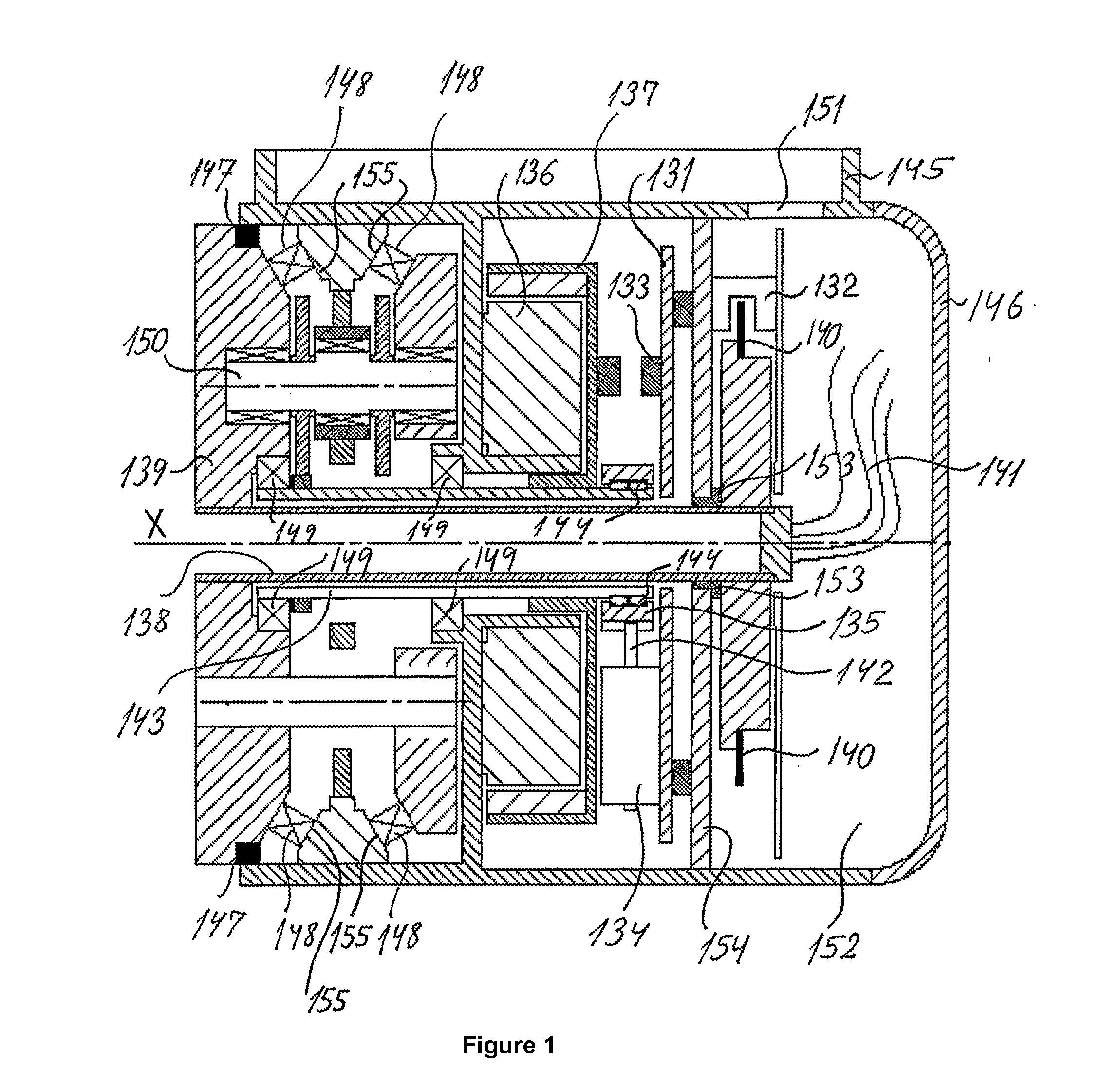
[0012]It is specifically an object of the present invention to provide a programmable robot system which can be programmed in a simple and easy manner without this requiring specialized knowledge, i.e. which can be performed for instance by an operator or technician in industry or even by a private person for instance at home. Specifically the safety control system utilizes two position sensors in each robot joint to achieve desired safety functions as will be explained in more detail below. The position sensors are used for sensing the angular or linear position on the input or output side of the gear or similar transmission device. If any violations of operational limits or errors in hardware or software is discovered by any of the safety functions, the robot will be brought to a safe state.
[0013]In accordance with the present invention the system is designed so that no single failure in either software or hardware can cause the robot to become dangerous. A common way of realizing this is to have two separate systems (branches) for performing the safety functions. Both of these systems can independently shut off power to the robot. Each of these systems can monitor the desired safety parameters.

Problems solved by technology

Generally, the programming of robots used in industry requires specialized knowledge and can only be performed by persons skilled in the art, often referred to as system integrators.
In connection with multi-purpose robots for use in industry or even at home some important safety issues still remain unsolved.
In this regard, the frictional torque fluctuates depending on the outside air temperature and the operating state of the robot, so estimating the frictional torque with a high precision is difficult.
Therefore, it was difficult to precisely detect collision between a human and a robot from the torques of the manipulator part of a robot and prevent harm to the human.
However, when a human directly contacts a robot without a carried object interposed between them, the force which occurs between the human and the robot is not detected.
Further, even if attaching a force sensor for detecting force between the arm and hand of a robot etc., it is not possible to detect contact of the human at the arm portion of the robot which the sensor cannot detect.
For this reason, in the prior art, it was not possible to provide a robot system which enabled safe interactive work when there was a possibility of a human and a robot coming into direct contact.
In addition to all electrically good conducting materials, capacitive sensors only detect those materials having an adequately high permittivity.
Capacitive sensors are not useful as a safety device in the case of rapidly moving apparatuses with solid parts moved freely in space.
A robot is a physical machine which can potentially be dangerous and cause harm to humans by colliding with them.
In case of hardware or software defects, the robot might even do unexpected motions, which were not anticipated by the system integrator (the person responsible for the safety when setting up the robot).
Torque sensors (such as straing gagues) are not applicable for obtaining a reliable safety control system.
Moreover, the sensors in US2010 / 0324733 are connected to two computing units S1, S2 in the form of integrated circuits (ICs), which have microcontrollers, within a transmitter unit S. Thus, US2010 / 0324733 does not have all sensor circuits placed on the same component, which renders it less applicable for safety control.

Method used


Image

  • Safety system for industrial robot
  • Safety system for industrial robot

Examples


Embodiment Construction

[0072]In accordance with the present invention the system is designed so that no single failure in either software or hardware can cause the robot to become dangerous.

[0073]A common way of realizing this is to have two separate systems for performing the safety functions. Both of these systems can independently shut off power to the robot. Each of these systems can monitor the desired safety parameters. The two systems should be as diverse as possible to avoid common cause failures. These failures could be compiler errors, methodology errors, software bugs, electronics glitches. To overcome this, the two branches of the safety system software is made by two independent teams of programmers, the source code is compiled by different compilers, and run on different microprocessors. The two branches use different hardware to measure the angular positions, and two different ways of cutting off the power supply in case of a failure.

[0074]Since the safety control system utilizes two sensor...


PUM


Abstract

A safety system for an industrial robot, specifically an industrial robot and a method for implementing a safety system via predefined safety functions. To perform such safety functions the robot comprises in a joint connecting two robot arm sections a first position sensor (132) for sensing the angular orientation on an input side of a gear in the joint, and a second position sensor (133) for sensing an angular orientation on an output side of the gear.

Description

FIELD OF THE INVENTION[0001]The present invention relates to robotic safety systems. More specifically the present invention is directed to an industrial robot implementing a safety system via predefined safety functions.BACKGROUND OF THE INVENTION[0002]Robots are extensively used in the industry for applications such as electronic circuit board assembly and other automated assembly tasks. The particularly high popularity of modern robots is attributed to their simple construction, low cost, low maintenance, light weight, high accuracy, high speed and compliance characteristics.[0003]Generally, the programming of robots used in industry requires specialized knowledge and can only be performed by persons skilled in the art, often referred to as system integrators. In connection with multi-purpose robots for use in industry or even at home some important safety issues still remain unsolved.[0004]A conventional robot system is provided with a collision detection function which detects ...

Claims


Application Information

Patent Timeline
Patent Type & Authority Applications(United States)
IPC IPC(8): B25J13/08B25J19/06B25J9/16
CPCB25J13/088B25J19/06B25J9/1674B25J13/08B25J19/0075B25J9/16
Inventor OESTERGAARD, ESBEN HZIEBA, GRZEGORZBRANDT, DAVID
Owner UNIVERSAL ROBOT
Why Eureka
Try Eureka