

Burner panels including dry-tip burners, submerged combustion melters, and methods
- Summary
- Abstract
- Description
- Claims
- Application Information
AI Technical Summary
Benefits of technology
Problems solved by technology
Method used
Image

Examples
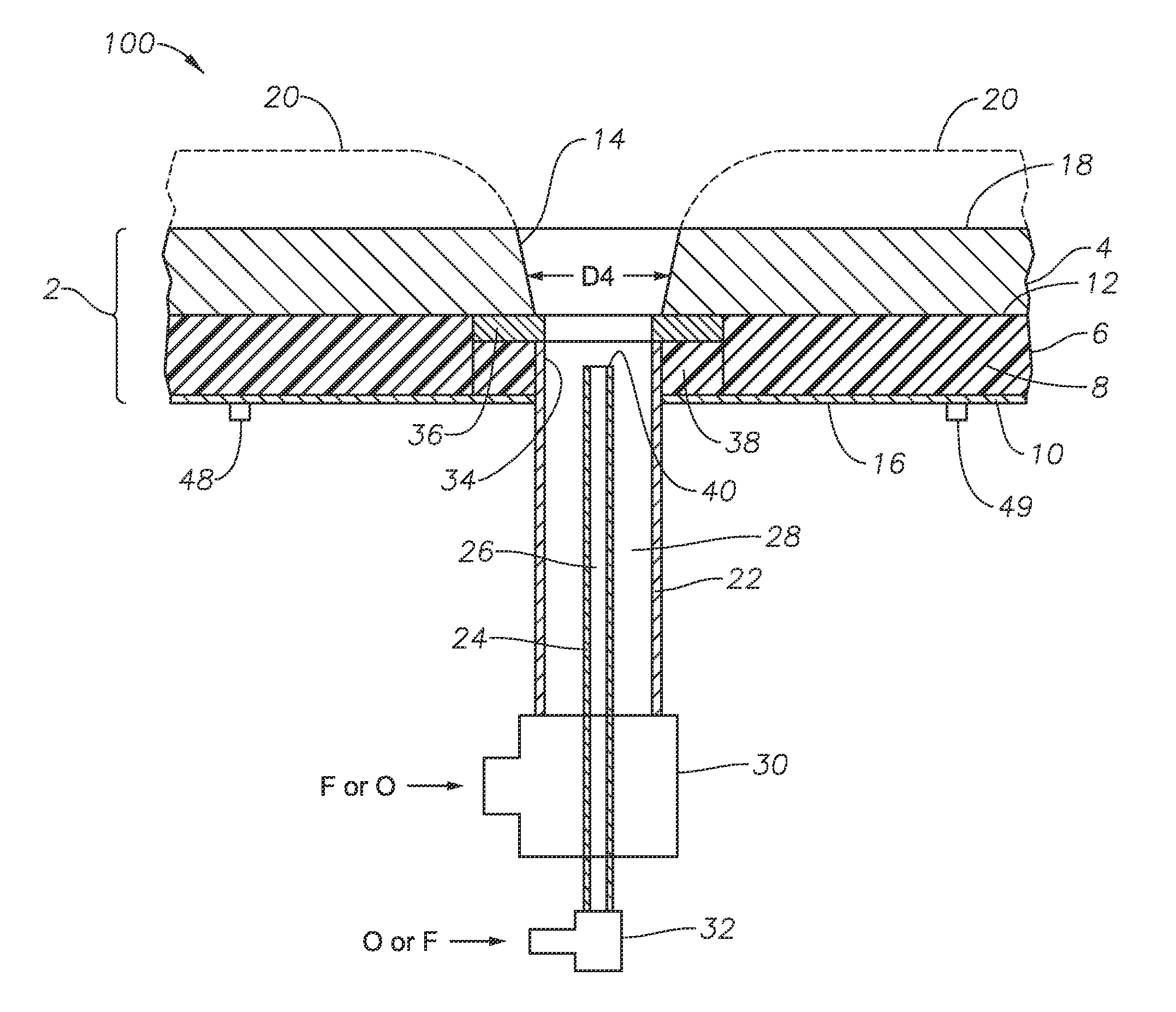
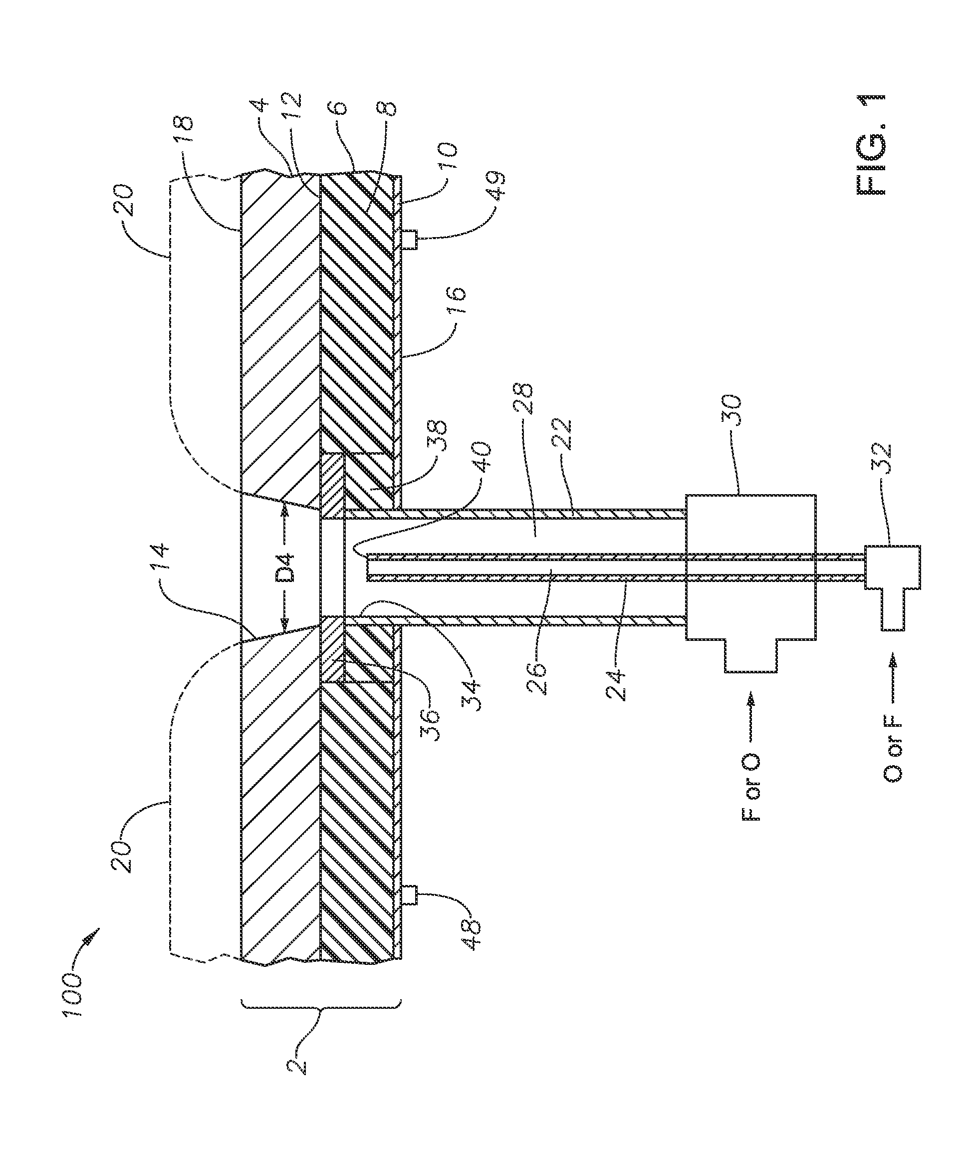
embodiment 100
[0054]Still referring to embodiment 100 and FIG. 1, burner panel 100 includes a plenum 30 through which outer conduit 22 maybe connected to a source of F or O, and a connector 32 for connecting inner conduit 24 to a source of F or O. At a distal end 34 of outer conduit 22 is associated a non-fluid-cooled protective member 36, which may be a shaped annular disk comprised of one or more noble metals. A distal end 40 of inner conduit 24 is illustrated, as well as coolant fluid inlet and outlet connections 48, 49.
[0055]Embodiment 100 illustrated in FIG. 1 also shows diameter D4 of though passage 14 through non-fluid-cooled portion or layer 4. Diameter 14 in embodiment 100 is illustrated as increasing in the direction of flow, but this is not necessary. The diameter D4 may initially be constant, but over time during operation may broaden as illustrated due to erosion. The rate of erosion may be controlled by selection of the material of non-fluid-cooled portion 4, or at least that portio...
embodiment 300
[0058]Referring now to FIGS. 5, 6, and 7, illustrated are three other embodiments 300, 400, and 500 of burner panels in accordance with the present disclosure. Embodiments 300, 400, and 500 illustrate embodiments employing a fluid-cooled protective member 72 fluidly connected to a supply of coolant fluid through one or more coolant fluid supply conduits 80, and fluidly connected to a return of coolant fluid through one or more return conduits 82. The designation “CFI” indicates “coolant fluid in” and the designation “CFO” means “coolant fluid out.” Embodiment 300 includes an outer conduit 22 having an expansion nozzle 70 attached thereto, for example by welding. Alternatively, nozzle 70 and outer conduit 22 may be formed from a single ingot of metal. Embodiments 300, 400, and 500 also illustrate the use of a mounting sleeve 74, mounting sleeve first half flange 76, and second half flange 78, the flange halves held together with appropriate bolts and gaskets, not illustrated. Conduit...
embodiment 600
[0063]System embodiment 600 further includes an exhaust stack 656, and submerged combustion fuel and oxidant conduits 24, 22, in one or more burner panels making up floor 200 which create during operation a highly turbulent melt indicated at 668 having a variable surface 669. In certain embodiments, fuel and oxidant conduits 24, 22 are positioned to emit fuel and oxidant into molten material in the melting zone 668 in a fashion so that the gases combust and penetrate the melt generally perpendicularly to floor panel 200. In other embodiments, one or more fuel or oxidant conduits 24, 22 may emit fuel or oxidant into the melt at an angle to floor 200, where the angle may be more or less than 45 degrees, but in certain embodiments may be 30 degrees, or 40 degrees, or 50 degrees, or 60 degrees, or 70 degrees, or 80 degrees.
[0064]The initial raw material can be introduced into the melter of system 600 on a batch, semi-continuous or continuous basis. In some embodiments, a port 660 is arr...
PUM
| Property | Measurement | Unit |
|---|---|---|
| Angle | aaaaa | aaaaa |
| Angle | aaaaa | aaaaa |
| Diameter | aaaaa | aaaaa |
Abstract
Description
Claims
Application Information