
Physical quantity measuring device

a technology of physical quantity and measuring device, which is applied in the direction of instruments, fluid pressure measurement, heat measurement, etc., can solve the problems of complicated waterproof structure and troublesome calibration work

Active Publication Date: 2017-03-02
NAGANO KEIKI
View PDF1 Cites 5 Cited by
  • Summary
  • Abstract
  • Description
  • Claims
  • Application Information

AI Technical Summary

Benefits of technology

The invention is a physical quantity measuring device that can easily calibrate its electronic unit after assembly. It has a simple waterproof structure and eliminates disturbances in wireless communication. It allows for easy setting and calibration of the electronics using a controller without a tool. The device has an engagement portion that ensures stable communication. It also has a window that provides a hermetical seal and eliminates disturbance for communication. Moreover, the device is designed for one-to-one signal transmission and reception with a controller even when multiple devices are used. Additionally, the device allows for accurate attachment of the communication attachment member.

Problems solved by technology

In addition, since the wireless communication is easily affected by disturbances (e.g. electric wave noise and optical noise), it is necessary to furnish an environment capable of stable communication.
Thus, when a zero point calibration and the like are to be performed, a volume adjuster has to be operated using a screwdriver, so that the calibration work becomes troublesome and complicated waterproof structure is required.

Method used


Image

  • Physical quantity measuring device
  • Physical quantity measuring device
  • Physical quantity measuring device

Examples


first exemplary embodiment

[0041]A first exemplary embodiment of the invention will be described below with reference to FIGS. 1 to 8.

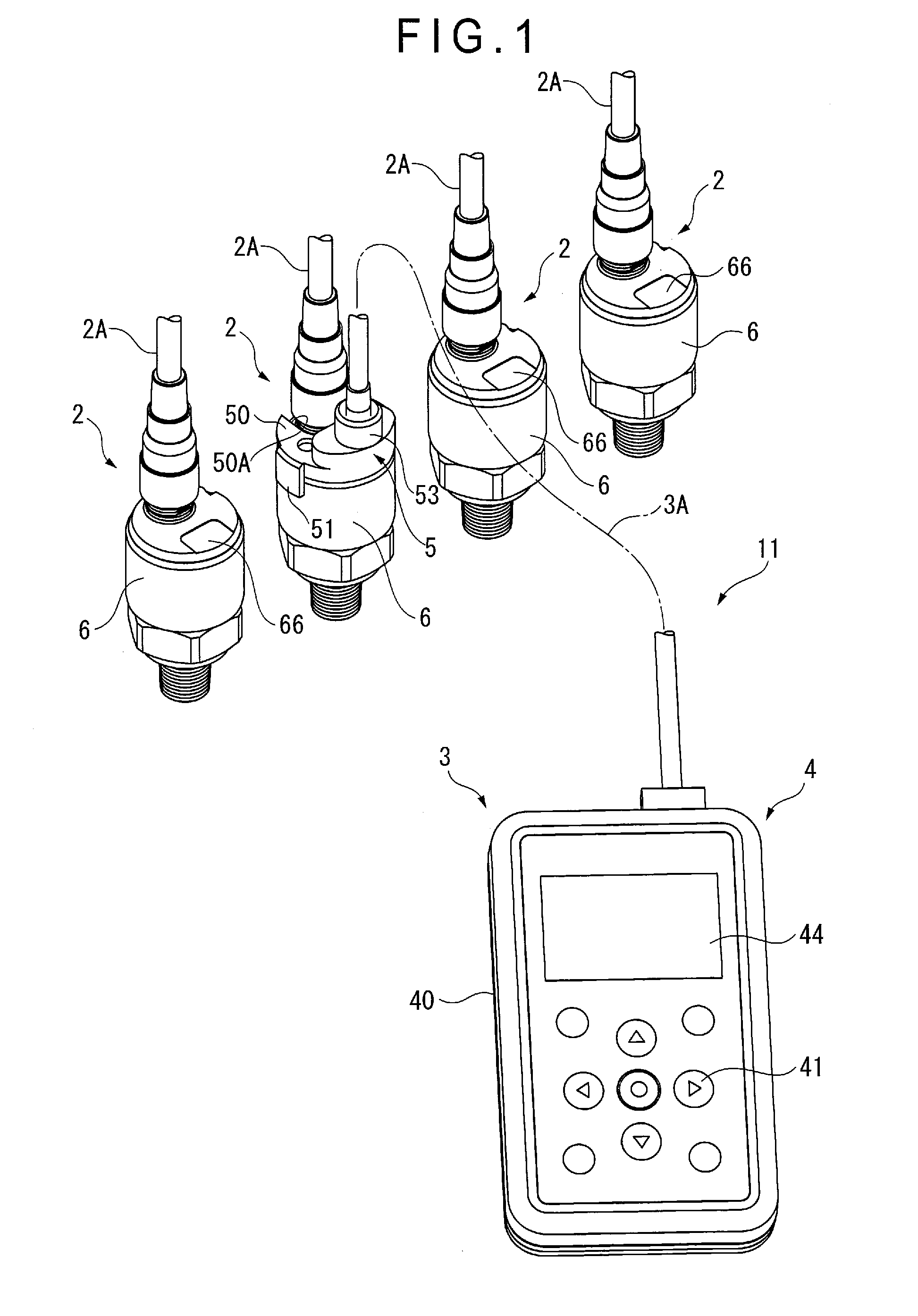
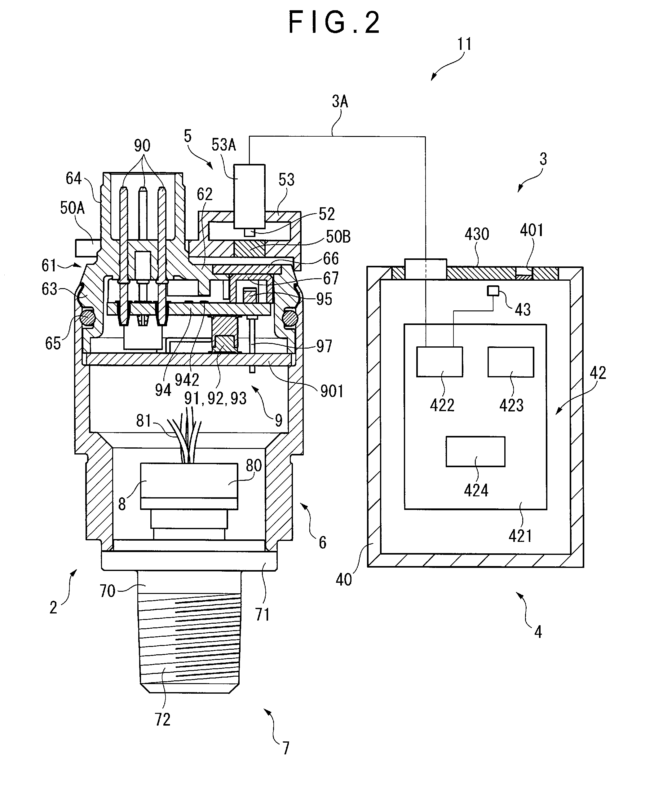
[0042]An overall arrangement of a physical quantity measuring device according to the first exemplary embodiment is shown in FIGS. 1 and 2.

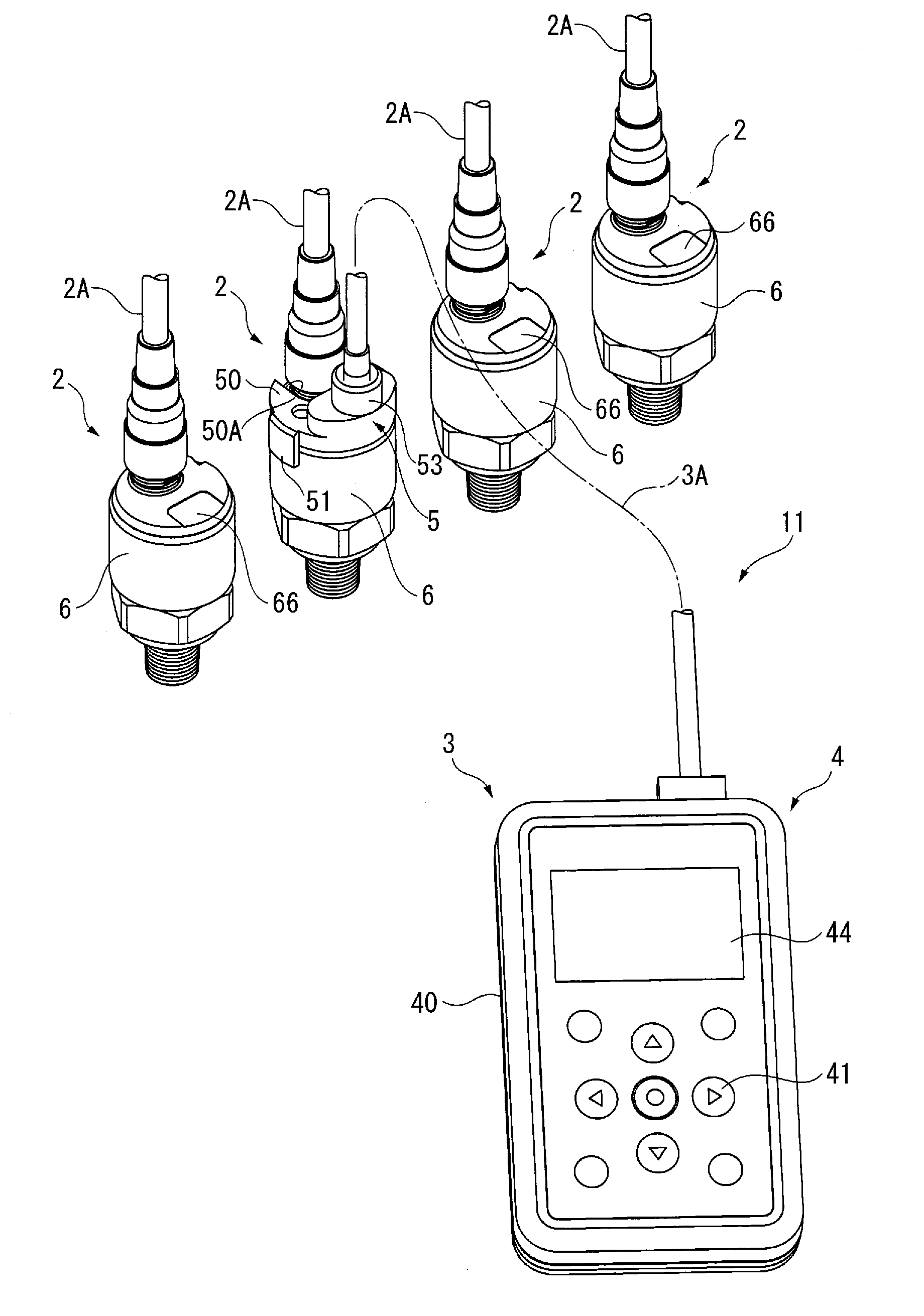
[0043]As shown in FIGS. 1 and 2, a physical quantity measuring device 11 includes a measuring device body 2 and a controller 3 attachable to the measuring device body 2. A plurality of measuring device bodies 2 are shown in FIG. 1 in the first exemplary embodiment, and the controller 3 is connected to one of the plurality of measuring device bodies 2.

[0044]The measuring device body 2 is a pressure measuring device configured to measure a pressure of a target fluid and transmit the measured pressure data to an outside through a cable 2A.

[0045]The controller 3 includes a controller body 4, a communication attachment member 5 configured to be detachably attached to the measuring device body 2, a second light emitter / receiver 52 provided to the ...

second exemplary embodiment

[0101]Next, a second exemplary embodiment of the invention will be described below with reference to FIG. 9.

[0102]A physical quantity measuring device 12 according to the second exemplary embodiment differs from that of the first exemplary embodiment in the arrangement of the controller and the arrangement of the measuring device body 2 is the same as that in the first exemplary embodiment. It should be noted that the same components as those in the first exemplary embodiment will be denoted using the same signs in the description of the second exemplary embodiment to omit the explanation thereof.

[0103]As shown in FIG. 9, the physical quantity measuring device 12 includes the measuring device body 2 and a controller 31 attached to the measuring device body 2.

[0104]The controller 31 includes a communication attachment member 54 detachably attached to the measuring device body 2.

[0105]The communication attachment member 54 includes a cover 55 provided with a second light emitter / recei...

third exemplary embodiment

[0112]Next, a third exemplary embodiment of the invention will be described below with reference to FIGS. 10 to 12. It should be noted that the temperature correction circuit 96 is not shown in FIG. 10.

[0113]A physical quantity measuring device 13 according to the third exemplary embodiment differs from that of the first exemplary embodiment in the arrangement of the controller and the arrangement of the measuring device body 2 is the same as that in the first exemplary embodiment. It should be noted that the same components as those in the first exemplary embodiment will be denoted using the same signs in the description of the third exemplary embodiment to omit the explanation thereof.

[0114]As shown in FIGS. 10 and 11, the physical quantity measuring device 13 includes the measuring device body 2 and a controller 32 attached to the measuring device body 2.

[0115]The controller 32 is an integrated component of a controller body 45 and a communication attachment member 59 and the cor...


PUM


Abstract

A controller includes: a communication attachment member configured to be detachably attached to a measuring device body; a second light emitter / receiver provided to a communication attachment member and configured to transmit / receive a signal to / from a first light emitter / receiver of the measuring device body; and a second controller configured to transmit / receive a signal to / from the second light emitter / receiver. An electronic circuit unit, electronic calibration unit, first control unit, signal transmission unit and the first light emitter / receiver are provided inside a housing of the measuring device body. A window is hermetically provided to a plate of the measuring device body. The communication attachment member includes a cover configured to be disposed so that the second light emitter / receiver faces the window and an engagement portion provided to the cover to be engageable with the housing.

Description

[0001]The entire disclosure of Japanese Patent Application No. 2015-172563 filed Sep. 2, 2015 is expressly incorporated by reference herein.TECHNICAL FIELD[0002]The present invention relates to a physical quantity measuring device.BACKGROUND ART[0003]Some of known physical quantity measuring devices include communication units through which measurement data is outputted to an outside.[0004]A typical example of such a physical quantity measuring device in a form of a pressure measurement device includes: a housing; a converter provided to the housing and configured to generate electric signals based on a pressure at an inlet; and a data communication device connected to the converter to transmit wireless signals in accordance with the electric signals (Patent Literature 1: JP-A-2006-510035).[0005]Another typical example of the physical quantity measuring device in a form of a temperature measurement unit includes: a closed housing that houses a sensor element for detecting physical q...

Claims


Application Information

Patent Timeline
IPC IPC(8): G01L27/00H04B10/69H04B10/079G01K19/00
CPCG01L27/002H04B10/0795H04B10/69G01K19/00G01L19/086G01L19/143
Inventor ITE, TAKAYUKISUZUKI, YASUYUKISUZUKI, TOSHINORIMURAMATSU, HIDEKI
Owner NAGANO KEIKI
Learn More