Method and device for determining a maximum change in a magnetic field in a magnetic resonance imaging scanner

a magnetic resonance imaging and maximum rate technology, applied in the direction of magnitude/direction of magnetic fields, measurements using magnetic resonance, instruments, etc., can solve the problems of generating hazardous voltages, destroying electric components, or at least experiencing functional impairment, so as to reduce the time required for real-time checking.

Inactive Publication Date: 2017-03-02
SIEMENS HEALTHCARE GMBH
View PDF0 Cites 6 Cited by
  • Summary
  • Abstract
  • Description
  • Claims
  • Application Information

AI Technical Summary

Benefits of technology

[0016]In this context it is also conceivable to replace the epsilon positive definite condition by the more precise condition ‘positive semidefinite’ for the matrix difference. This reduces the epsilon dependent added safety margin to the maximum rate of change in a magnetic field to a minimum.
[0017]However, the epsilon positive semidefinite condition advantageously provides that the magnitudes of the magnetic fields plus an added margin for the partial volume Vj that is dependent upon the bound ε are greater for all activation signals I than those for the volume V1. Hence, a calculation of the magnetic field magnitude for the volume Vj provides the maximum value for the respective group. Under the epsilon positive semidefinite condition, the value ε for the difference matrices may be used to shift the maximum value that may not be exceeded upward in dependence on □, wherein simultaneously there may be an increase in the number of matrices MB1 whose differences from MBj are epsilon positive semidefinite. Thus, this advantageously enables the number of groups, and hence also the time required for checking in real time, to be reduced, wherein in exchange the activation signals have to be reduced by the deduction of a safety margin dependent on ε.

Problems solved by technology

Strong magnetic fields in conjunction with rapid changes may result in the generation of voltages that may be hazardous in a variety of ways.
There are implanted electric devices, such as, for example pacemakers, cochlea implants as hearing aids or even drug pumps or dosing devices that may not be removed during an examination and the malfunction of which may endanger the health or life of the patient.
These devices have electric components that may be destroyed or at least experience functional impairment due to induced voltages.
In addition, imaging would be no longer possible or would at least be greatly impaired in a region that is screened to a greater or less degree.
Further, voltages may be induced on metallic implants in teeth or joints and result in undesirable movements or sensations of pain.

Method used


Image

  • Method and device for determining a maximum change in a magnetic field in a magnetic resonance imaging scanner
  • Method and device for determining a maximum change in a magnetic field in a magnetic resonance imaging scanner
  • Method and device for determining a maximum change in a magnetic field in a magnetic resonance imaging scanner

Examples


Embodiment Construction

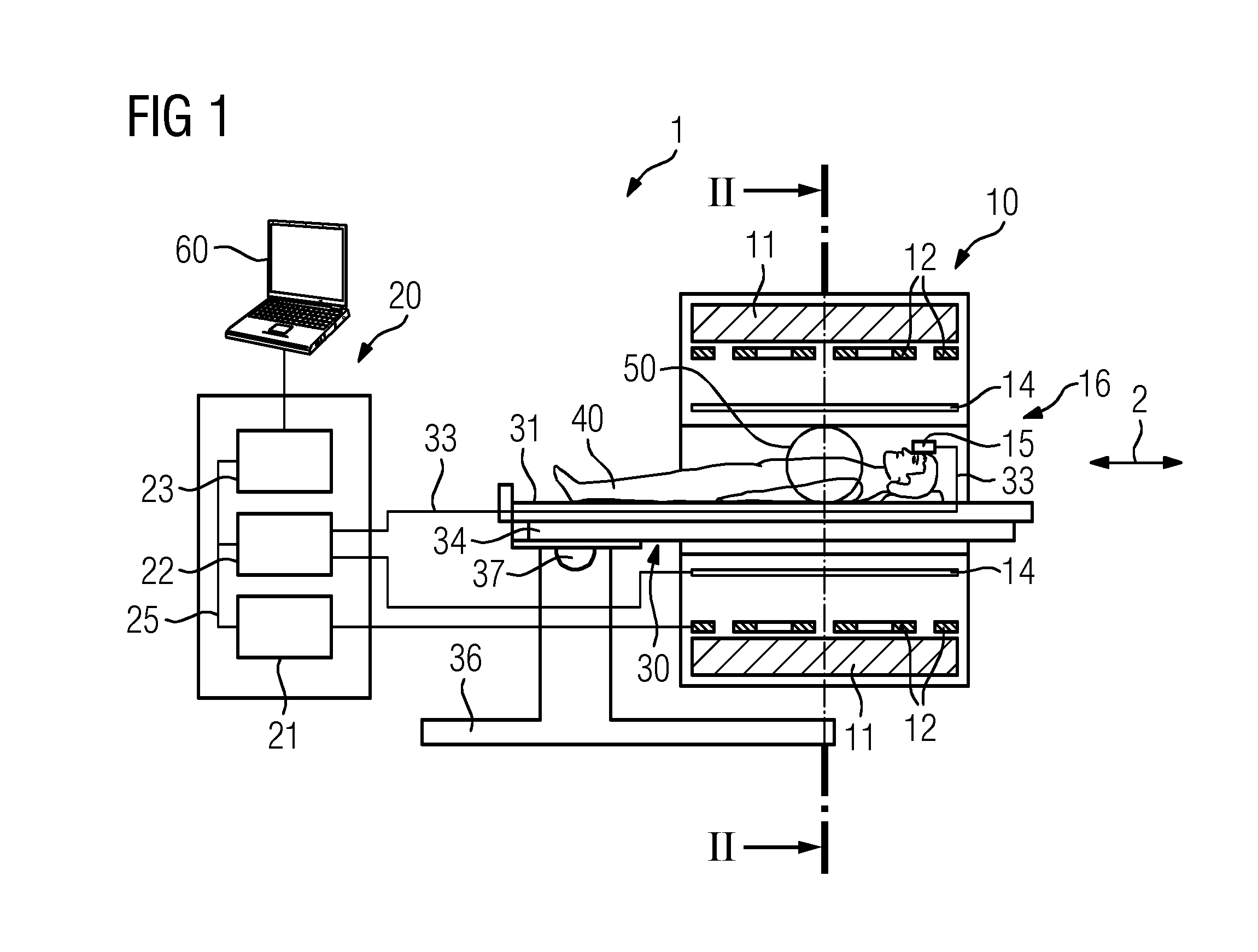
[0050]The magnet unit 10 includes a field magnet 11 that generates a static magnetic field B0 for the alignment of nuclear spins in specimens or patients 40 in an examination volume. The examination volume is arranged in a leadthrough 16 extending in a longitudinal direction 2 through the magnet unit 10. The field magnet 11 is may be a superconducting magnet that is able to provide magnetic fields with a magnetic flow density of up to 3T or even more with the most recent devices. However, it is also possible to use permanent magnets or electromagnets with normally conducting coils for lower field strengths.

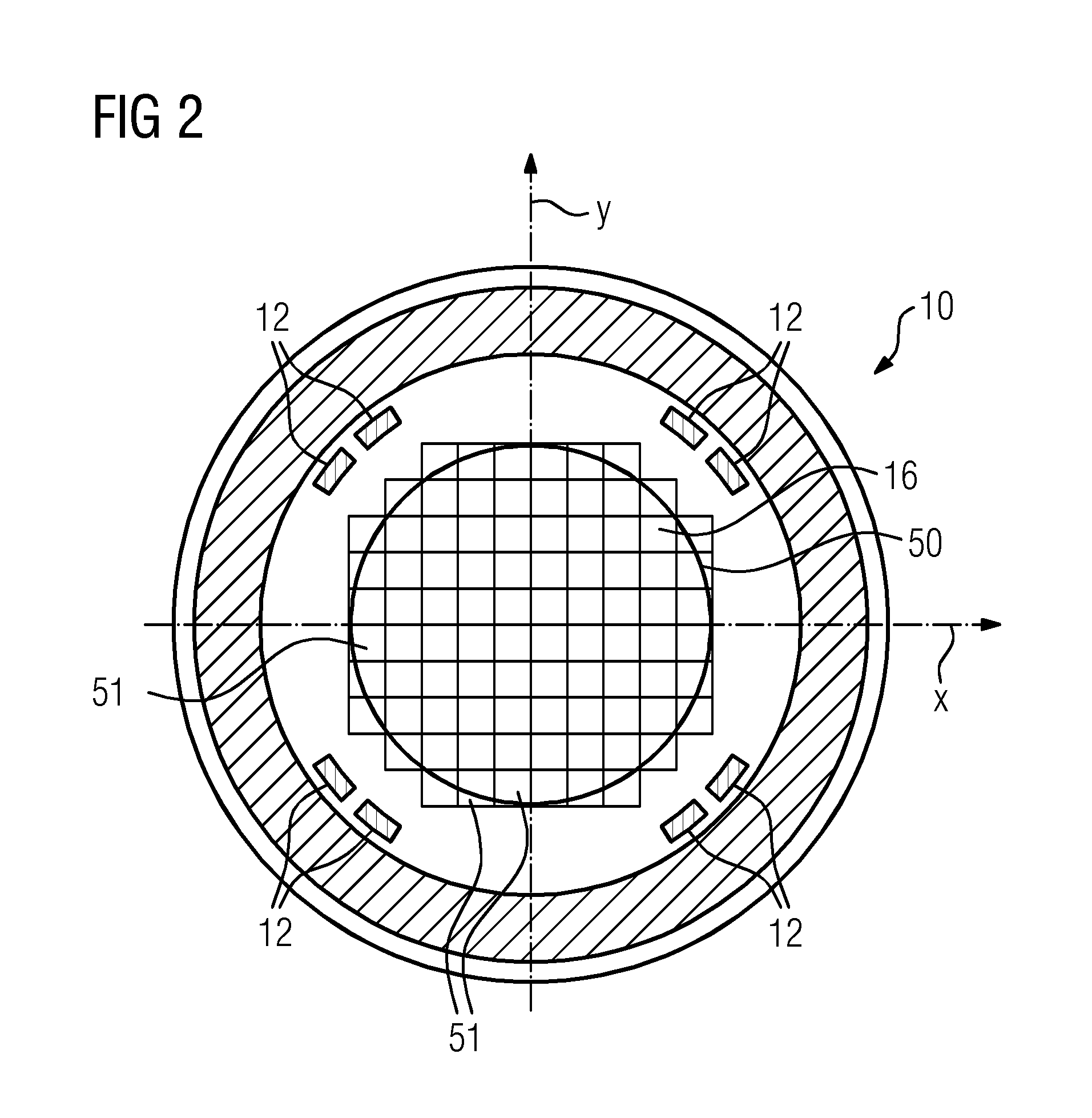
[0051]The magnet unit 10 further includes gradient coils 12 designed, for the spatial differentiation of the image region in the examination volume, to superimpose the magnetic field B0 with variable magnetic fields in three spatial directions. The gradient coils 12 may be coils made of normally conducting wires able to generate fields that are orthogonal to one another in the exa...


PUM


Abstract

A method and system for determining a maximum function for a magnetic resonance imaging scanner. The maximum function indicates the upper bound of a magnetic field magnitude in an examination volume in dependence on activation signals of magnetic coils acting on the examination volume. The examination volume is divided into a plurality of partial volumes. The method determines matrices (MB), which, when multiplied by a vector of the activation signals of the magnetic coils, indicate a resultant square of the magnetic field magnitude for each partial volume.

Description

CROSS REFERENCE TO RELATED APPLICATIONS[0001]This application claims the benefit of DE 10 2015 216 323.7, filed on Aug. 26, 2015, which is hereby incorporated by reference in its entirety.TECHNICAL FIELD[0002]Embodiments relate to a method for determining a maximum rate of change in a magnetic field for a magnetic resonance imaging scanner. The maximum rate of change in a magnetic field determined indicates an upper bound of a rate of change in a magnetic field in an examination volume in dependence on activation signals of magnetic coils acting on the examination volume.BACKGROUND[0003]Magnetic resonance imaging scanners are imaging devices that to depict an object under examination align nuclear spins in the object under examination with a strong external magnetic field and excite them by a magnetic alternating field to precession about this alignment. The precession or return of the spins from this excited state into a low energy state in turn generates a response in the form of ...

Claims


Application Information

Patent Timeline
Patent Type & Authority Applications(United States)
IPC IPC(8): G01R33/24G01R33/54G01R33/28
CPCG01R33/24G01R33/543G01R33/288G01R33/385
Inventor GEBHARDT, MATTHIASRUYTERS, GUDRUN
Owner SIEMENS HEALTHCARE GMBH
Why Eureka
Try Eureka