Method and machine for treating textile fabrics with an adjustable air flow

a textile fabric and air flow technology, applied in the direction of liquid/gas/vapor treatment of propelled fabrics, lighting and heating apparatus, drying machines with progressive movements, etc., can solve the problem of not allowing the intensity of the impact to be reduced without also reducing the flow rate and drying speed. , to achieve the effect of reducing the intensity of the impact of the fabric, reducing the transport speed and impact force, and less mechanical action

Inactive Publication Date: 2017-03-09
BIANCALANI SRL
View PDF0 Cites 5 Cited by
  • Summary
  • Abstract
  • Description
  • Claims
  • Application Information

AI Technical Summary

Benefits of technology

[0016]The solution proposed allows reducing the intensity of the impact of the fabric against the grilles while maintaining unchanged the total air flow acting on the fabric and without interrupting its alternating motion in

Problems solved by technology

The machine last mentioned, although it allows a lower frequency of fabric impact against the grilles to be obta

Method used


Image

  • Method and machine for treating textile fabrics with an adjustable air flow
  • Method and machine for treating textile fabrics with an adjustable air flow
  • Method and machine for treating textile fabrics with an adjustable air flow

Examples


Embodiment Construction

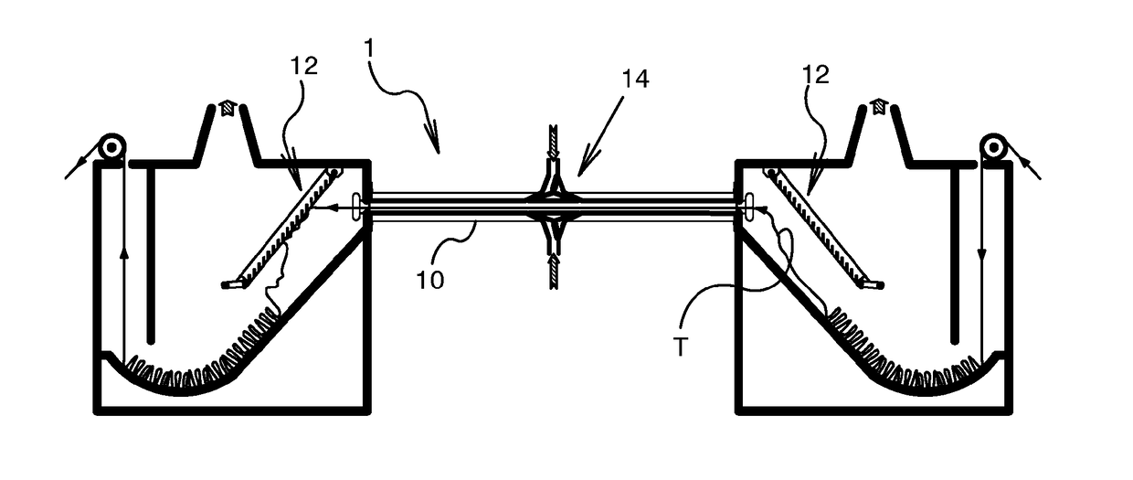
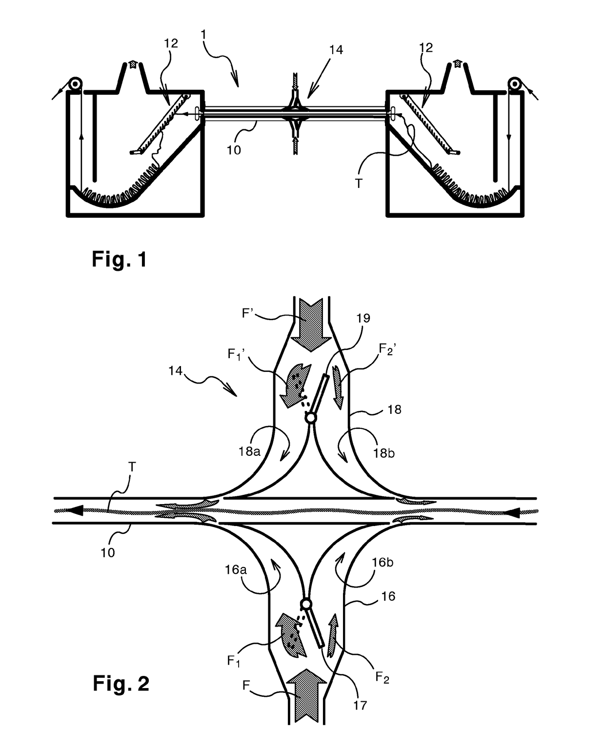
[0025]FIG. 1 shows the schematic longitudinal cross section of a continuous open-width tumbler 1 which is equipped with a rectangular-section tunnel 10 for pneumatically transporting a fabric T and with impact grilles 12 facing the openings of the tunnel. Located substantially half way along the tunnel 10, typically above and below the fabric, is the system 14 for injecting air into the tunnel. The air flow is generated by means, not illustrated, of essentially known type.

[0026]This system 14—shown enlarged and in more detail in FIG. 2—comprises two diverting valves 16,18, each having two channels 16a,16b and 18a,18b which are suitably oriented to direct the air flow entering the tunnel in one direction or the other. According to the invention, each valve also comprises an adjustable baffle 17,19 adapted to shut off access to the channels 16a,16b and 18a,18b, either wholly or partly.

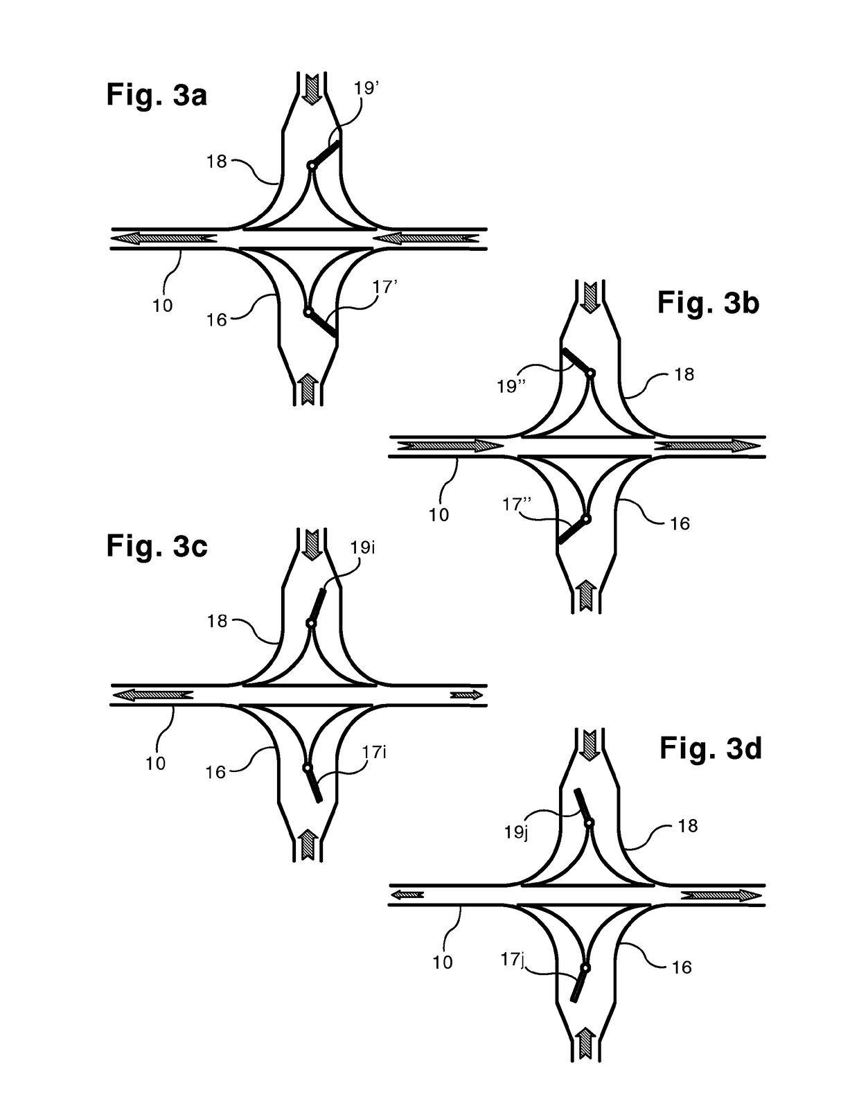
[0027]As a result, the valves 16,18 can operate in two distinct modes.

[0028]In effect, each baffle 17...


PUM


Abstract

A machine for treating a fabric (T) with air, comprises a tunnel (10) for pneumatically transporting the fabric and means for injecting the air into the tunnel above and/or below the fabric and comprising at least one diverting valve (16;18) located substantially half way along the tunnel and having two channels (16a,16b;18a,18b) which are oriented to direct the air flow entering the tunnel in one direction or the other. The valve comprises an adjustable baffle (17;19) adapted to shut off access to the channels (16a,16b;18a,18b) either wholly or partly. In the treatment method of the invention, the air flow (F;F′) entering the tunnel is divided into two unequal components (F1, F2; F1′, F2′) directed towards opposite ends of the tunnel.

Description

TECHNICAL FIELD[0001]This invention relates to a method and a machine for treating textile fabrics with an adjustable air flow.PRIOR ART[0002]In the finishing of textile fabrics, it is common practice to use continuous, open-width machines (tumblers) for treating the fabrics to obtain fibre swelling, and a soft pleasant hand for fabrics of all kinds.[0003]These machines comprise a straight air tunnel and at least one flow diverter baffle movable between two limit positions to convey all the air in the tunnel in one direction or the other alternately.[0004]That way, the fabric is transported at high speed towards one or the other of the tunnel openings and transferred alternately to one or the other of the two heaps at the two ends of the tunnel.[0005]Impact grilles suitably positioned in front of the two openings of the transport tunnel bring the fabric to a stop while allowing the air to continue towards two hoods above the heaps.[0006]Systems for slowly transferring the fabric, at...

Claims


Application Information

Patent Timeline
IPC IPC(8): D06B3/28D06C19/00
CPCD06C19/00D06B3/28B65H20/14F26B13/103
Inventor BIANCALANI, MASSIMORAVAGLI, RICCARDO
Owner BIANCALANI SRL
Why Eureka
Try Eureka