
Reaction Cuvette Loading Device and Chemiluminescence Immunoassay Apparatus

a technology of immunoassay and loading device, which is applied in the field of external diagnostic equipment, can solve the problems of difficult popularization and promotion of the apparatus, high cost of the commonly used biochemical luminescence measurement apparatus, and large volume, and achieve the effect of reducing the volume of the product, shortening the movement time duration of the push rod, and reducing the movement range of the push rod

Active Publication Date: 2017-03-09
SHENZHEN NEW INDS BIOMEDICAL ENG
View PDF0 Cites 6 Cited by
  • Summary
  • Abstract
  • Description
  • Claims
  • Application Information

AI Technical Summary

Benefits of technology

The invention provides a reaction cuvette loading device that can reduce the amount of product needed. This is achieved by using a guiding control block to control the push rod to return to its original position after the cuvette pushing action, resulting in a shorter movement time and reduced volume of product needed.

Problems solved by technology

However, the commonly used biochemical luminescence measurement apparatus is expensive and has a huge volume, and a greater power consumption, it difficult to popularize and promote the apparatus.
However, in the process of practical use, the inventor found that the conventional reaction cuvette loading device has the following disadvantages: when the push rod pushes the reaction cuvette, in order to bypass the reaction cuvette on the cuvette pushing position, the movement range of the push rod occupies a space of at least two cuvette positions, causes the overall volume of the product to be huge, such that a greater space is occupied.

Method used


Image

  • Reaction Cuvette Loading Device and Chemiluminescence Immunoassay Apparatus
  • Reaction Cuvette Loading Device and Chemiluminescence Immunoassay Apparatus
  • Reaction Cuvette Loading Device and Chemiluminescence Immunoassay Apparatus

Examples


Embodiment Construction

[0020]The above and other objects, features and advantages of the present invention will become more apparent by describing in detail with reference to the accompanying drawings. It should be understood that the specific embodiments described herein are only used to explain the invention and is not intended to limit the invention.

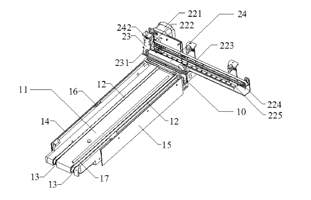
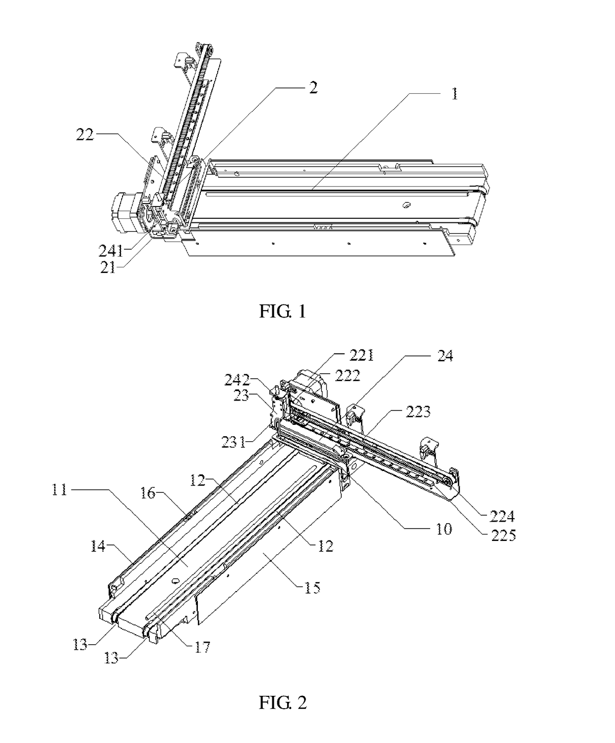
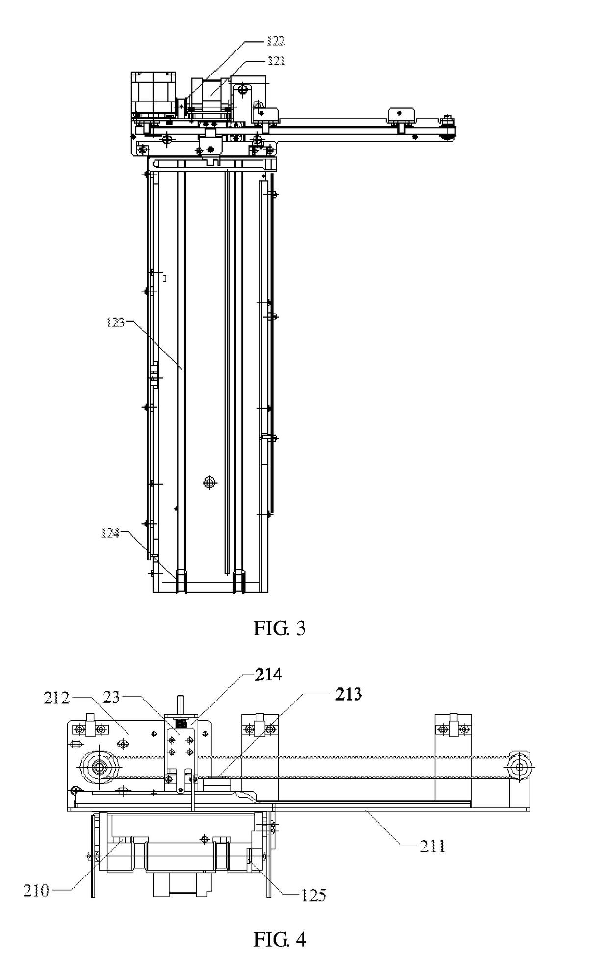
[0021]A reaction cuvette loading device according to one embodiment is specifically illustrated with reference to FIG. 1 through FIG. 5. As shown in FIG. 1 and FIG. 2, the embodiment includes a transmission mechanism 1 and a pushing mechanism 2. The transmission mechanism 1 includes a bottom plate 11; a first horizontal transmission mechanism 12 positioned on the bottom plate 11; and a transmission groove 13 positioned on the bottom plate 11 and configured to receive the horizontal transmission mechanism 12. The push mechanism 2 includes a bracket assembly 21, a second horizontal transmission mechanism 22 positioned on the bracket assembly 21, a push rod 23...


PUM

PropertyMeasurementUnit
inclined angleaaaaaaaaaa
distanceaaaaaaaaaa

Abstract

Provided are a reaction cuvette loading device and a fully automatic chemiluminescence immunoassay apparatus. The reaction cuvette loading device comprises a transmission mechanism and a push mechanism, wherein the transmission mechanism comprises a baseplate and a first horizontal transmission mechanism provided on the baseplate; the push mechanism comprises a support assembly, a second horizontal transmission mechanism provided on the support assembly, and a push rod connected to the second horizontal transmission mechanism; and the push mechanism further comprises a direction guiding control block comprising a starting end provided at a terminal point of a cuvette pushing stroke of the push rod, a termination end provided at a starting point of the cuvette pushing stroke of the push rod, and a return track provided between the starting end and the termination end and bypassing the cuvette pushing stroke, and the separation distance between the starting end and termination end is not less than one vessel position and not more than two vessel positions.

Description

FIELD OF THE INVENTION[0001]The invention relates to an external diagnostic apparatus, and more particular relates to a reaction cuvette loading device and a chemiluminescence immunoassay apparatus using the reaction cuvette loading device.BACKGROUND OF THE INVENTION[0002]Biological chemiluminescence immunoassay is a non-radio immunoassay which is established by adopting a tracer ray machine as a signal tracer, based upon the theoretical basis of radio immunoassay; it processes advantages of a high sensitivity, a wider limiting scope, an easy operation and it is easy to realize an automatic operation. At present, a biochemical luminescence measurement apparatus based upon biological chemiluminescence immunoassay is a widely-used medical diagnostic apparatus. However, the commonly used biochemical luminescence measurement apparatus is expensive and has a huge volume, and a greater power consumption, it difficult to popularize and promote the apparatus. Due to a high-speed development...

Claims


Application Information

Patent Timeline
Patent Type & Authority Applications(United States)
IPC IPC(8): G01N33/53G01N35/04G01N21/76
CPCG01N33/5304G01N21/76G01N2035/0467G01N2035/0401G01N2035/0482G01N35/04G01N35/02G01N2035/0465G01N2035/0484
Inventor RAO, WEIBAN, DINGPINGYI, WANGUANZHU, LIANGHU, YICHEN, XIAOTAOYIN, LILIN, WEI
Owner SHENZHEN NEW INDS BIOMEDICAL ENG
Learn More