Manifold system and synthesis of a manifold system from input models

a manifold system and input model technology, applied in the field of manifold system and input model synthesis, can solve the problems of not scaling well for parallel processing involving multi-dimensional heterogeneous nodes, models fail to take into account the temporal and spatial parallelism inherent in problem space, computational space and relationship, and optimal solution

Inactive Publication Date: 2017-03-09
SANKHYA TECH PTE LTD
View PDF0 Cites 11 Cited by
  • Summary
  • Abstract
  • Description
  • Claims
  • Application Information

AI Technical Summary

Benefits of technology

[0058]According to yet another embodiment of the invention, a declarative programming language is provided to model multitude of planes of compute elements, cognitive element elements, transducer elements, relationship elements and problem data elements as components of a manifold system and also to support the modeling of the projection of the planes of manifold elements to other planes of manifold elements. This allows the concurrency inherent in the problem to be directly modeled instead of the procedural approach used in existing methods to model the solution as a sequential program which is then made to execute in

Problems solved by technology

While this model works well for sequential program execution, however, it does not scale well for parallel processing involving multi-dimensional heterogeneous nodes.
These models fail to take into account the temporal and spatial parallelism inherent in the problem space, computational space and in the relationships between the different elements of the system.
This approach may not result in an optimal solution since it does not have explicit information at the source level on which parts of the

Method used


Image

  • Manifold system and synthesis of a manifold system from input models
  • Manifold system and synthesis of a manifold system from input models
  • Manifold system and synthesis of a manifold system from input models

Examples


example 1

[0187]A program which shows the use of the extensions described above. The program declares a channel named U. Within the channel, two transitive elements rin and rout are defined. The model statement specifies that st_ops is a namespace consisting of space-time operator mappings defined in the space-time model file fm_st.md.

[0188]A hard progressive muladd is declared with an interface consisting of two sensor inputs x and y and one sensor-activator z. The progressive block east defined inside muladd uses the st_ops model to specify the computations performed on the inputs x, y and z. The inputs x and y are declared as temporal indicating that they are a stream of values that is accessed over time. The progressive block core specifies that the mul operation defined in st_ops is invoked with x and y as its inputs and the result is assigned to t. The value t and z are then passed to the add operation defined in st_ops and the result is assigned to z.

[0189]The soft progressive dotp is ...

example 2

[0199]A sample C program which makes use of the manifold system defined in the program of example 1 to compute vector dot product. A manifold system component cf1 of type dotp_manifold is declared. In the main( )function, first the input vectors x and y are initialized. Then the different ports of the dotp_manifold system are invoked to map the data manifold into the computational manifold to compute the dot product of the input vectors.

Sample C program: / * Include required header files * / int x[10], y[10], z;U::dotp_manifold cf1;#define BIGDATASIZE 100000000int bigx[BIGDATASIZE], bigy[BIGDATASIZE];main( ){  / * Initialize input vectors x and y - Code not shown * /   / * Simple dot product * /  cf1.dot_product(x, y, 10, z); printf (″%x\n, z);  / * Large dot product in parallel parts * /  cf1.big_dot_product(bigx, bigy, BIGDATASIZE, z); printf (″%x\n, z);  / * 1-shot A dot-product * /  cf1.tele_product(x, y, 10, z); printf (″%x\n, ro1.z);}

example 3

[0200]A program described using the below language to model matrix multiplication may also be considered. The program declares a channel MM in which two progressives MultiplyMC and matrix_mul are defined. The Multipl yMC progressive takes a matrix m1 and a column vector as inputs and a product vector as output. The east block of the progressive declares a using statement to initialize all the elements of the product vector to zero. Another using statement is declared to multiply each row of m1 with the column vector m2 and to store the resulting row in the product vector. A transitive m2d is declared with a two dimensional array m as its member.

[0201]The progressive matrix_mul describes a compute element which takes two transitives m1, m2 of type m2d as input and has a transitive product as output. The east block of the progressive declares an array RowMul of type MultiplyMC. The using statement in this block models the projection of matrix m1.m and the slice m2.m to the array of co...


PUM


Abstract

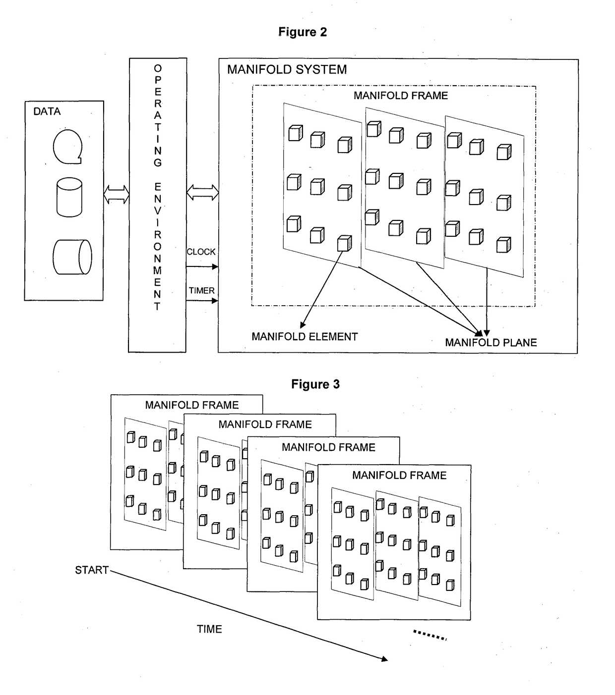
The present invention relates to a manifold system comprising: at least one manifold frame comprising an initial manifold configuration model, and a set of manifold planes, wherein each manifold plane comprises of a set of manifold elements, said manifold element is a concrete specialization of an abstract dimensioned entity supporting manifold operations such as configuration, projection, forming and transforming, etc, wherein such specializations comprises of compute elements, cognitive elements, transitive elements, processors, and/or transducer elements, or composite of these elements or composite of planes of these elements, etc, and variably progresses from manifold frame to frame in manifold time units through manifold system operations such as forming, transforming, projecting, computing, learning and transducing, etc in a real, virtual or a combination of real and virtual operating environment such as desktop operating system, distributed operating system, embedded operating system, field programmable gate array system, virtual system, and/or combination of real and virtual systems thereby performing useful work or duty. The present invention also relates a method of realizing a manifold system from input models.

Description

FIELD OF THE INVENTION[0001]This invention relates to computer architecture, computer architecture modeling, computer architecture synthesis, high performance computing, parallel computing, topological computing, many-core systems and programming. In particular, the invention relates to a manifold system and synthesis of a manifold system from input models.BACKGROUND OF THE INVENTION[0002]Many existing computers use what is termed as Von Neumann architecture and execute a program as a sequence of instructions accessed from memory through use of a program counter. These are termed as SISD computers. There are others that allow a single operation to be performed on multiple data streams (SIMD) often called vector processors or multiple operations to be performed on a single data stream (MISD). A general purpose parallel computer is like many SISD computers running in parallel and can be classified as multi-processor or many-core systems. Multi-instruction and / or multi-data (MIMD) stre...

Claims


Application Information

Patent Timeline
IPC IPC(8): G06F17/50G06F17/16
CPCG06F17/50G06F2217/16G06F17/16G06F2111/10G06F30/00G06F30/20
Inventor BULUSU, GOPI KUMARDESIKAN, MURALI
Owner SANKHYA TECH PTE LTD
Why Eureka
Try Eureka