

Electric tool
- Summary
- Abstract
- Description
- Claims
- Application Information
AI Technical Summary
Benefits of technology
Problems solved by technology
Method used
Image

Examples
first embodiment
[0031]Hereinafter, an illustrative embodiment of the present invention will be described with reference to the drawings. In the following drawings, an impact wrench is used as an example of an electric tool, the same components are denoted by the same reference numerals and a duplicated description thereof is omitted. Further, as used herein, an upper-lower direction, a left-right direction and a front-rear direction are described as directions shown in the drawings.
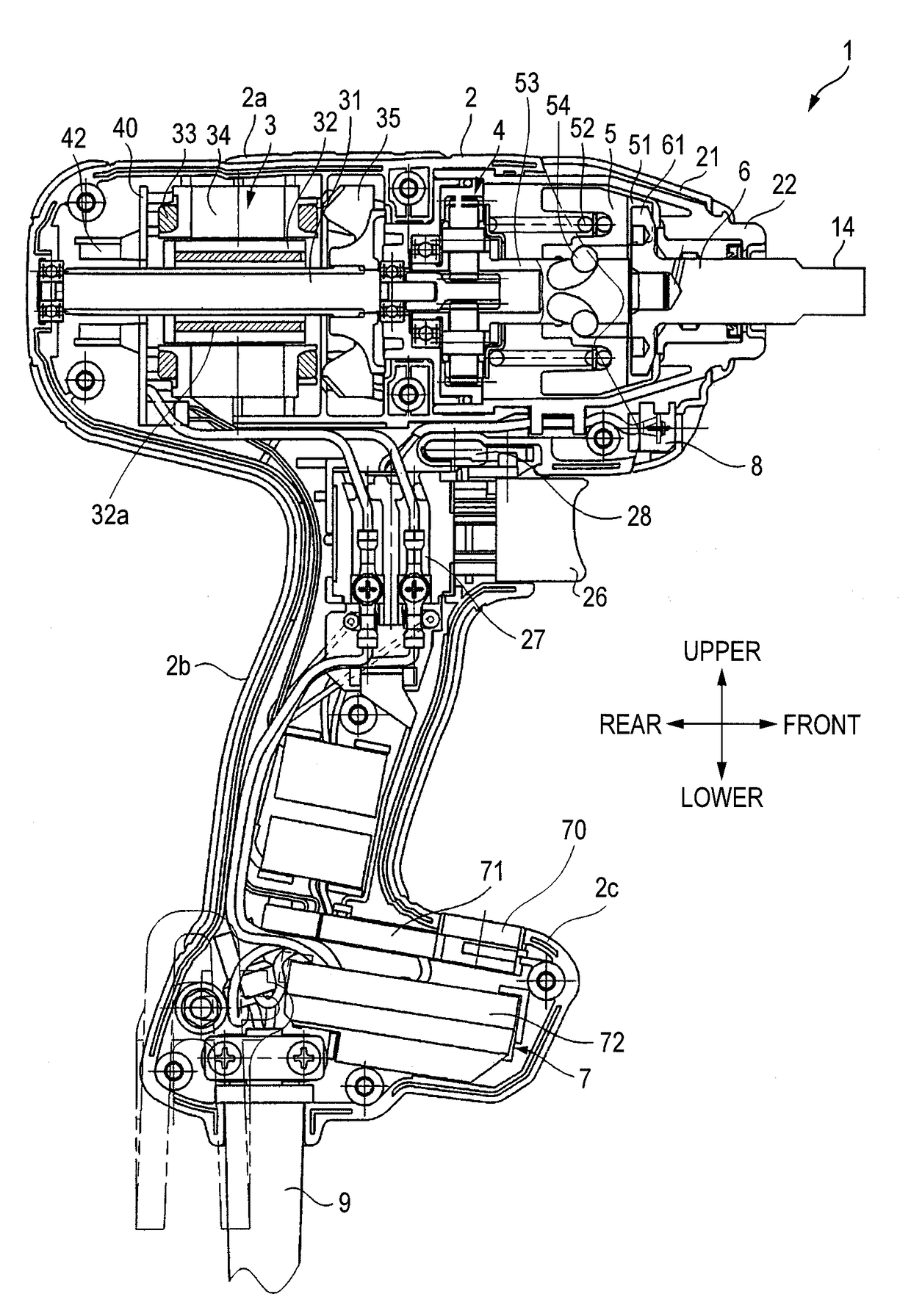
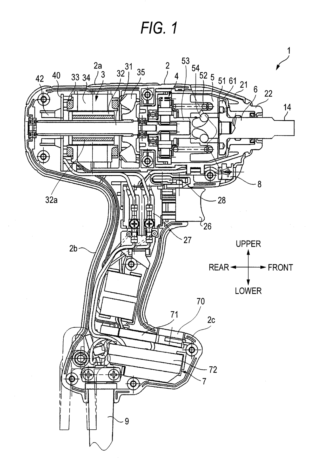
[0032]As shown in FIG. 1, an impact wrench 1 includes a housing 2, a motor 3, a deceleration mechanism 4, a hammer 5, an anvil 6, a light 8, a control unit 7 and a power supply cord 9. An end tool (not shown) is mounted to the anvil 6 that is an output shaft. FIG. 1 shows a mounting part 14 to which a hexagon socket as an end tool can be mounted. However, instead of the mounting part 14, a mounting hole and a mounting mechanism may be provided, to which a driver bit with a hexagonal cross-section or other end tools can b...
second embodiment
[0049]Next, a rotation control procedure of a motor according to a second embodiment of the present invention will be described with reference to the flowchart of FIG. 7. The basic control procedure in the second embodiment is the same as in the first embodiment. However, the measuring procedure for the no-load input voltage V0 in the second embodiment is different from the first embodiment. That is, instead of periodically measuring the no-load input voltage V0 when the power supply voltage is connected, the no-load input voltage V0 is measured for a short time immediately after the pulling of the trigger and before the rotation start of the motor 3. Here, a state of the motor 3 before the start refers to a state before current flows through the motor 3 and a state of the motor 3 after the start refers to a state where current flows through the motor 3. First, the power supply cord 9 of the impact wrench 1 is connected to the socket 105 or the cord reel 103, so that the microcomput...
third embodiment
[0051]Next, a rotation control procedure of a motor according to a third embodiment of the present invention will be described with reference to the flowchart of FIG. 8. As shown by a step group 700, the control before the start of the motor in the third embodiment is the same as in the second embodiment. However, in Step 701′ of the third embodiment, an operation of assigning 0.118(Ω) to Z is executed, as an impedance value Z0 for computing the voltage drop of the extension cord. This value may be previously stored in the ROM 84b of the operation unit 81. The other steps are the same as the steps 702 to 706 in the second embodiment and a duplicated description thereof is thus omitted. When the average value of the no-load input voltage V0 sampled by the number of N times after the pulling of the trigger is calculated by the step group 700, the duty ratio D0 (%) is computed by using the formula (1) (Step 801).
D0=230 / (average V0 value)×86 (formula 1)
[0052](Here, D0=100 when the com...
PUM
 Abstract
Description
Claims
Application Information