Laminated air circulation board

Inactive Publication Date: 2017-03-16
COLLINS P MICHAEL
View PDF4 Cites 10 Cited by
  • Summary
  • Abstract
  • Description
  • Claims
  • Application Information

AI Technical Summary

Benefits of technology

[0010]The sockets of the panel create dedicated spaces for drainage and air circulation thereby minimizing the conditions that promote mold growth in the cavity between the two walls. The laminated board eliminates bridging, as described above, and provides an air conduit to exhaust even the minimal amounts of vapor that will occur in the cavity. A self-sealing tape may be applied to the interface between the inner wall and cupped depressions so that when fasteners penetrate the board, the small annular space created by the fastener shank is sealed from leakin

Problems solved by technology

One potentially catastrophic result of bridging between the inner and outer walls is trapped moisture in that layer of the wall assembly by interfering with the free flow of water which in turn and over time reduces or negates the beneficial physical properties of the air and moisture protection.
Furthermore, wetting can saturate insulations which negate their thermal properties.
Although theses nettings and fabrics may perform to a degree of their clai

Method used


Image

  • Laminated air circulation board
  • Laminated air circulation board
  • Laminated air circulation board

Examples


Embodiment Construction

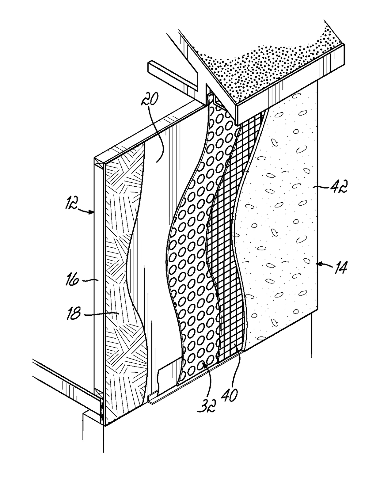
[0019]One embodiment of this invention is used in a cavity wall 10 construction environment. As shown in U.S. Pat. No. 7,421,826, which is hereby incorporated by reference in its entirety, brick veneer / cavity walls 10 are made with inner and outer walls 12, 14. The inner wall 12 is typically constructed from CME, wood or steel studs 16 with an interior surface of drywall or the like. The outer face of the inner wall 12 typically includes a layer of sheathing 18 such as plywood, particle board or the like, that is nailed to the studs 16. Commonly, a weather resistant or air barrier material 20 covers the sheathing material 18 to limit moisture from progressing through the inner wall 12. The outer wall 14 is generally constructed of masonry materials 22, such as bricks, stone or the like, that are held together by mortar 24. Common practice in many municipal building codes requires a space of at least ⅜ to one inch forming a cavity 26 between the inner and outer walls 12, 14. The reas...


PUM


Abstract

A laminated board is secured to the inner wall of a cavity wall construction to establish a defined spacing between the inner and outer walls and prevent excess mortar from bridging to the inner wall. The laminated board has a series of spaced sockets into which fasteners may project into the face of the inner wall or framing thereof to secure the outer wall. The board is installed prior to the construction of the outer wall and establishes a minimum spacing or gap between the walls based upon the thickness of the board. The outer wall is constructed immediately adjacent to the outer face of the laminated board. The board is impervious and eliminates bridging by the mortar, eliminates transfer of bulk water from the exterior finish to the inner wall and provides an air conduit to exhaust even the minimal amounts of vapor that will occur in the cavity.

Description

[0001]This is a continuation in part of U.S. patent application Ser. No. 15 / 213,700 filed Jul. 19, 2016, which claimed the benefit of U.S. Provisional Patent Application Ser. No. 62 / 194,322, filed Jul. 20, 2015 and each of these prior applications is hereby incorporated by reference in its entirety.BACKGROUND OF THE INVENTION[0002]This invention relates to exterior finishes on buildings, utilizing lath as part of the exterior finish system and, more particularly, to an impervious device used in construction of those exterior finish systems that establishes drainage and air circulation pathways which effectively mitigate wet conditions, which often lead to mold growth.[0003]Stucco and thin veneer brick or stone are popular exterior finish systems. Such wall assemblies often include inner and outer walls. The inner structural wall is typically constructed from concrete masonry units (CMU), wood or steel studs with an interior surface of drywall or the like. The outer face of CMU inner...

Claims


Application Information

Patent Timeline
IPC IPC(8): E04B1/70E04B2/44E04C2/34E04C2/04E04C2/06E04B2/02E04B2/48
CPCE04B1/7038E04B2/02E04B2/44E04B2/48E04C2002/3416E04C2/044E04C2/06E04C2/3405E04C2002/3472E04B1/7076E04F13/045E04F13/047E04C2002/3427E04C2/32
Inventor COLLINS, P. MICHAEL
Owner COLLINS P MICHAEL
Why Eureka
Try Eureka