Life Estimation Circuit and Semiconductor Device Made Using the Same

a technology of life estimation and circuit, which is applied in the direction of individual semiconductor device testing, semiconductor operation lifetime testing, transistors, etc., can solve the problem of inability to accurately estimate and achieve the effect of accurate detection and accurate estimation of the life of power elements

Active Publication Date: 2017-03-16
MITSUBISHI ELECTRIC CORP
View PDF10 Cites 13 Cited by
  • Summary
  • Abstract
  • Description
  • Claims
  • Application Information

AI Technical Summary

Benefits of technology

[0010]Therefore, a main object of the present invention is to provide a life estimation circuit capable of accurately estimate the life of a power element, and a semiconductor device made using the same.
[0012]In the life estimation circuit according to the present invention, an inflection point of temperature variation in the power element is detected, an absolute value of a difference between the temperature of the power element at an inflection point detected this time and the temperature of the power element at an inflection point detected last time is determined, the number of times of occurrence of a first temperature variation in which the absolute value reaches a first threshold temperature is counted, and a signal related to the life of the power element is output based on the count value. Accordingly, thermal stress applied to the power element can be accurately detected, so that the life of the power element can be accurately estimated.

Problems solved by technology

In Patent Document 1, therefore, the thermal stress applied to the power element is underestimated, resulting in inability to accurately estimate the life of the power element.

Method used


Image

  • Life Estimation Circuit and Semiconductor Device Made Using the Same
  • Life Estimation Circuit and Semiconductor Device Made Using the Same
  • Life Estimation Circuit and Semiconductor Device Made Using the Same

Examples


first embodiment

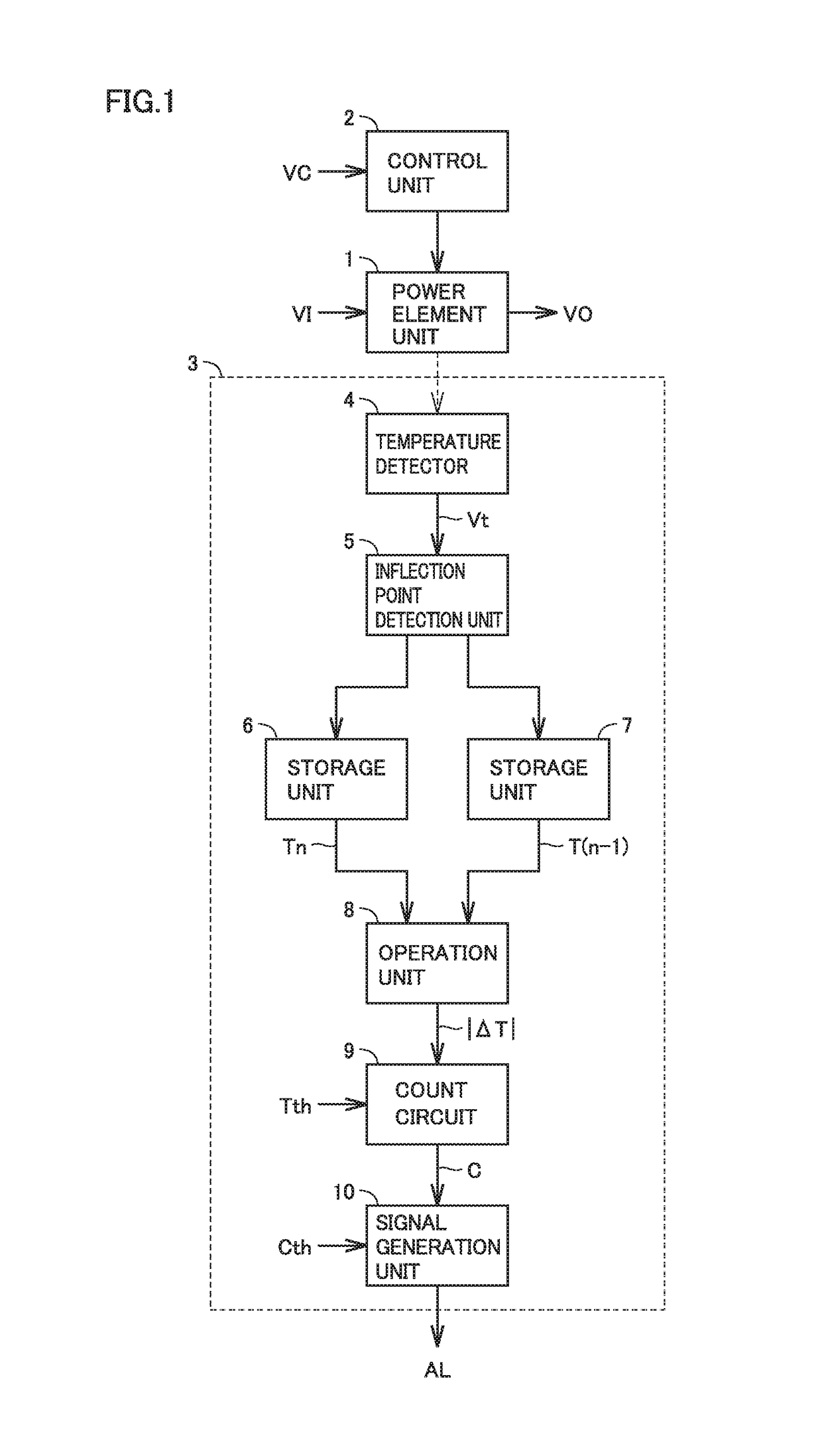
[0022]FIG. 1 is a block diagram showing the configuration of a power module according to a first embodiment of the present invention. In FIG. 1, this power module includes a power element unit 1, a control unit 2, and a life estimation circuit 3.

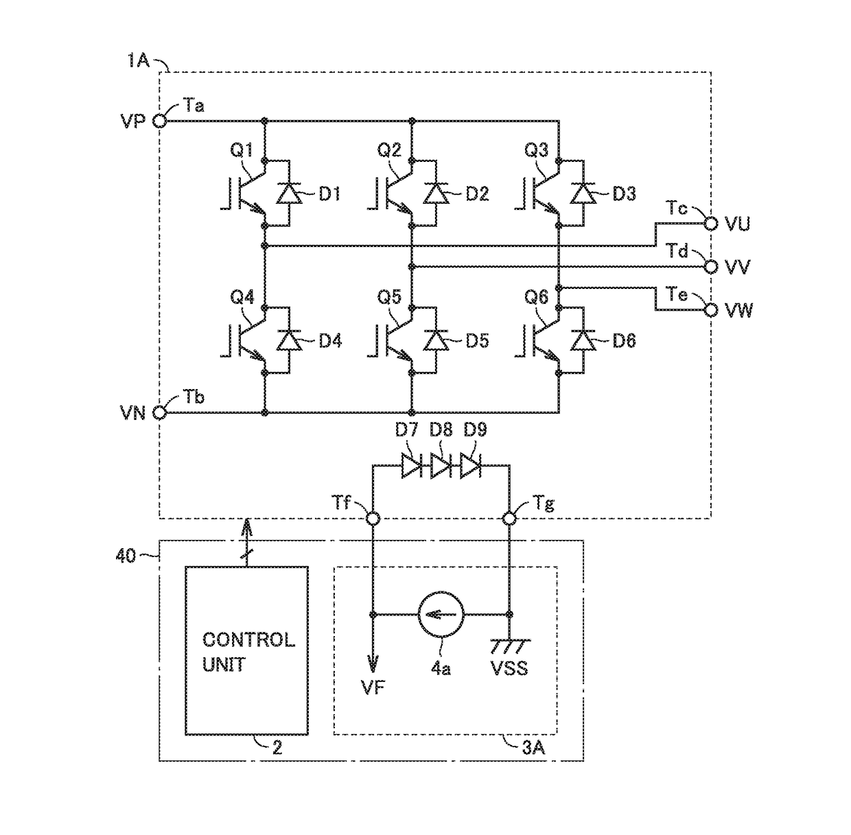
[0023]Power element unit 1 includes a plurality of power elements, is controlled by control unit 2, and converts a direct-current (DC) voltage VDC into an alternating-current (AC) voltage VAC, for example. The power elements are IGBTs (Insulated Gate Bipolar Transistors), MOSFETs, bipolar transistors, diodes or the like.

[0024]Control unit 2 coverts DC voltage VDC into sinusoidal AC voltage VAC by turning each of the plurality of power elements of power element unit 1 on / off based on, for example, a sinusoidally varying voltage command value VC. When a current is passed through the power element, loss (namely, heat) occurs in the power element, whereby the temperature of the power element increases. When the current flowing through the power ...

second embodiment

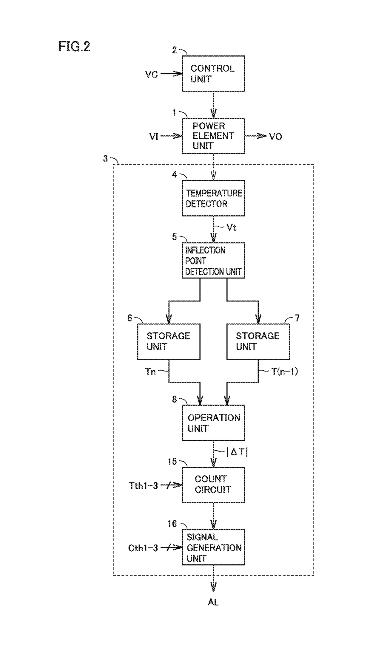
[0038]FIG. 2 is a block diagram showing the configuration of a power module according to a second embodiment of the present invention, which is compared with FIG. 1. With reference to FIG. 2, this power module is different from the power module shown in FIG. 1 in that count circuit 9 and signal generation unit 10 have been replaced with a count circuit 15 and a signal generation unit 16, respectively.

[0039]Count circuit 15 compares first to third threshold temperatures Tth1 to Tth3 with absolute value |ΔT| of the temperature difference determined by operation unit 8, and determines which one of first to third temperature variations ΔT1 to ΔT3 has occurred based on results of the comparisons. Tth1>Tth2>Tth3 holds. When Tth11 has occurred. When Tth21 is satisfied, it is determined that second temperature variation ΔT2 has occurred. When Tth32 is satisfied, it is determined that third temperature variation ΔT3 has occurred.

[0040]Count circuit 15 increments (+1) a first count value C1 w...

third embodiment

[0055]FIG. 4 is a block diagram showing the configuration of a power module according to a third embodiment, which is compared with FIG. 1. With reference to FIG. 4, this power module is different from the power module shown in FIG. 1 in that signal generation unit 10 has been replaced with a signal generation unit 20. Signal generation unit 20 outputs a digital signal DO indicating a difference Cth−C between threshold number of times Cth and count value C. Digital signal DO serves as a signal indicating an allowable number of times that a temperature variation occurs, that is, the remaining life of power element unit 1.

[0056]In this third embodiment, maintenance of the system, replacement of the power module and the like can be performed in a planned manner based on signal DO indicating the remaining life of power element unit 1.

[0057]Furthermore, since digital signal DO indicating the remaining life of power element unit 1 is output, the circuit size can be reduced, the number of ...


PUM


Abstract

A life estimation circuit includes a temperature detector configured to detect temperature of a power element unit, an inflection point detection unit configured to detect an inflection point of temperature variation in the power element unit based on an output signal from the temperature detector, an operation unit configured to determine an absolute value of a difference between the temperature of the power element unit at an inflection point detected this time and the temperature of the power element unit at an inflection point detected last time, a count circuit configured to count the number of times that the absolute value of the difference in temperature has reached a threshold temperature, and a signal generation unit configured to output, when a count value from the count circuit reaches a threshold number of times, an alarm signal indicating that the power element is about to reach the end of its life.

Description

BACKGROUND OF THE INVENTION[0001]Field of the Invention[0002]The present invention relates to life estimation circuits and semiconductor devices made using the same, and particularly to a life estimation circuit to estimate the life of a power element and a semiconductor device made using the same.[0003]Description of the Background Art[0004]A power element is subject to repeated, wide temperature variations as a current passing therethrough increases or decreases. As a result of the temperature variations, bonding of wires connecting the power element to electrodes gradually deteriorates and ultimately breaks, causing the power element to reach the end of its life. The wide temperature variations exert stress on solder connecting the components, causing the development of cracking and peeling which will lower the heat dissipation characteristics of the power element, sometimes even resulting in thermal destruction.[0005]However, since a power element is applied to a wide variety of...

Claims


Application Information

Patent Timeline
Patent Type & Authority Applications(United States)
IPC IPC(8): G01R31/26H01L27/06H01L29/739H01L29/16H01L29/861
CPCG01R31/2642H01L29/16H01L29/1608G01R31/2632H01L29/7393H01L27/0635G01R31/2608H01L29/861
Inventor UOTA, SHIORITAMETANI, FUMITAKAINOUE, TAKAHIROYONEYAMA, REI
Owner MITSUBISHI ELECTRIC CORP
Why Eureka
Try Eureka