See-Through Near-to-Eye Viewing Optical System

an optical system and near-to-eye technology, applied in the direction of stereophonic arrangments, instruments, earpiece/earphone attachments, etc., can solve the problems of short service life, poor color saturation and poor picture quality of lcd displays, and so complex manufacturing processes

Inactive Publication Date: 2017-03-16
SYNDIANT
View PDF5 Cites 6 Cited by
  • Summary
  • Abstract
  • Description
  • Claims
  • Application Information

AI Technical Summary

Benefits of technology

[0008]To achieve the aforesaid objective, the present invention provides a see-through near-to-eye viewing optical system, in which one or more light emitting diode (LED) illumination systems are used to generate a light, the light is concentrated by one or more pre-polarizers to a polarization beam splitter ...

Problems solved by technology

However, the LCD displays have poor color saturation and poor picture quality, and the OLEDs have a short service life and a high cost and the manufacturing process thereof is so complex that they cannot be produced in mass.
Further, the conventional see-through near-to-eye viewing optical systems are not used with other sound or light producing elements to provide more effects.
Consequently, it is impossible for the user to use the conventional see-through near-to-eye viewing optical systems with sound and images synchronously so as to receive in real time and merge visual and auditory senses and immediately output integrated inf...

Method used


Image

  • See-Through Near-to-Eye Viewing Optical System
  • See-Through Near-to-Eye Viewing Optical System
  • See-Through Near-to-Eye Viewing Optical System

Examples


first embodiment

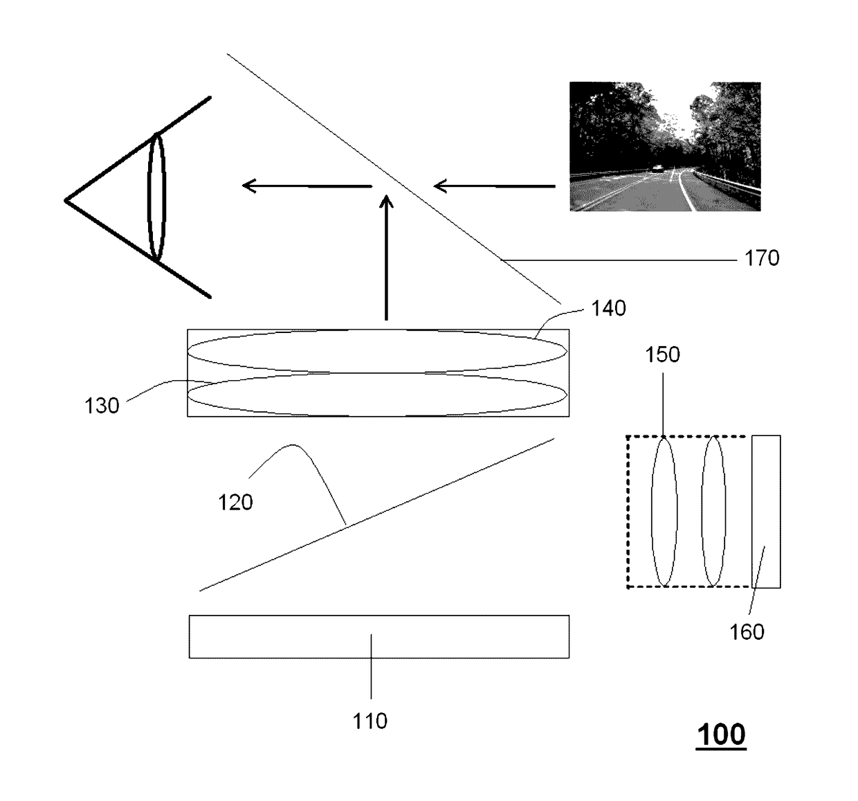
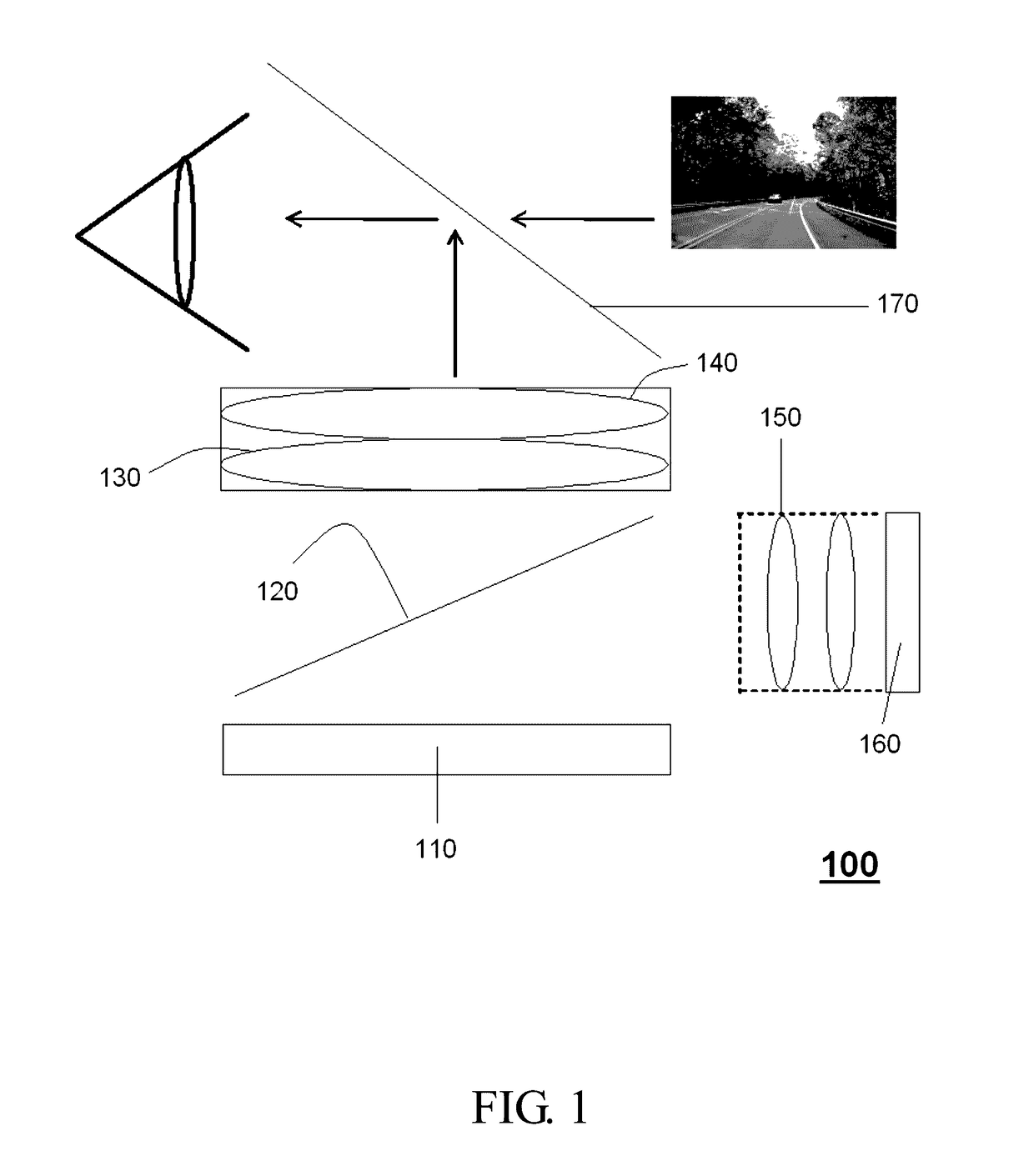
[0018]FIG. 1 is a schematic view of the present invention, which illustrates a front appearance of a see-through near-to-eye viewing optical system 100 of the color filter type. In the embodiment shown therein, the see-through near-to-eye viewing optical system 100 comprises an LCOS panel 110, a PBS 120, a post-polarizer 130, an eyepiece 140, a pre-polarizer 150, a white LED illumination system 160 and a beam splitter 170. The LCOS panel 110 comprises a color filter (not shown). When a light is generated by the white LED illumination system 160, the light is concentrated by the pre-polarizer 150 to the PBS 120 and is then reflected by the PBS 120 to the color filter of the LCOS panel 110 where the white light is split into a red light, a green light and a blue light. Then the LCOS panel 110 receives an image from the drive system board (not shown) and projects the image to the post-polarizer 130 and the eyepiece 140 so that the image is magnified by the eyepiece 140 and outputted vi...

second embodiment

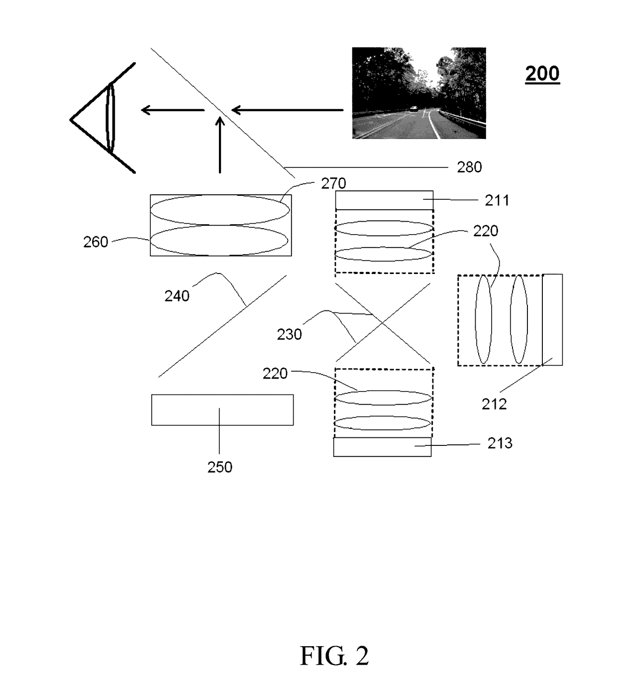
[0019]The present invention further provides a see-through near-to-eye viewing optical system 200 of the color sequential type in a second embodiment, a schematic view of which is shown in FIG. 2. The optical system 200 comprises an LCOS panel 250, a PBS 240, a plurality of pre-polarizers 220, a post-polarizer 260, a diachronic mirror 230, an eyepiece 270, a blue LED illumination system 211, a green LED illumination system 212 and a red LED illumination system 213. The blue LED illumination system 211, the green LED illumination system 212 and the red LED illumination system 213 each output a light to a respective pre-polarizer 220. The light is concentrated by the respective pre-polarizer 220 to the dichroic mirror 230 and reflected by the dichroic mirror 230 to the PBS 240, and is then reflected by the PBS 240 to the LCOS panel 250. The LCOS panel 250 receives the image from the drive system board (not shown) and projects the image to the post-polarizer 260 and the eyepiece 270 so...

third embodiment

[0021]In the present invention, a see-through near-to-eye viewing optical system 310 is used, together with image sensors 320 and a drive system board 360, in a see-through head-mounted augmented reality display system 200. FIG. 3A is a front view of this embodiment, and FIG. 3B is a rear view of this embodiment. In this embodiment, an external image is captured by two image sensors 320 and transmitted to the drive system board 360, and then the drive system board 360 processes the external image into a single or a multiple image for output to two optical systems 310. The numbers of the image sensors 320, the drive system board 360 and the optical system 310 are not limited to what described above. Further, the single image includes the external image, an internal image downloaded or stored by the drive system board 360, and an integrated image obtained by integrating the external image and the internal image. The multiple image includes Picture by Picture (PBP) images displayed res...


PUM

PropertyMeasurementUnit
Angleaaaaaaaaaa
Volumeaaaaaaaaaa
Frequencyaaaaaaaaaa

Abstract

A see-through near-to-eye viewing optical system, which can be used in a head-mounted augmented reality display system, is provided. The see-through near-to-eye viewing optical system of the present invention comprises an LED illumination system for generating a light and a pre-polarizer for concentrating said light onto a PBS. Then an LCOS panel receives and reflects said light towards a post-polarizer after generating an image. The light travels from the post-polarizer and passes through an eyepiece for magnifying the image, and continues towards a 50/50 beam splitter. Afterwards the beam splitter transmits said light and another light from the outside field of view to user's eyes simultaneously and thus, the user can see what is shown on the glass screen while still being able to see through it.

Description

[0001]This application claims priority to Taiwan Patent Application No. 104130129 filed on Sep. 11, 2015.CROSS-REFERENCES TO RELATED APPLICATIONS[0002]Not applicable.BACKGROUND OF THE INVENTION[0003]Field of the Invention[0004]The present invention relates to a see-through near-to-eye viewing optical system, and more particularly, to a vertical see-through near-to-eye viewing optical system that employs a beam splitter to provide an image and that can be used in a head-mounted augmented reality display system.[0005]Descriptions of the Related Art[0006]The see-through viewing optical system is a kind of device that allows a user to view both an external image and a projection image simultaneously to achieve the effect of superimposing the real image and the virtual image on each other without masking the field of view. Some conventional see-through viewing optical systems use liquid crystal displays (LCDs) or organic light emitting diodes (OLEDs) as display elements. However, the LCD...

Claims


Application Information

Patent Timeline
IPC IPC(8): G02B27/01G06T19/00G02B1/04H04R1/10G02B27/28G02B27/22
CPCG02B27/0172G02B27/283G02B27/2214G02B1/04H04R1/1041G02B27/0176G02B2027/0156G02B2027/0116G02B2027/0138G02B2027/014H04R2420/01G02B2027/0154G06T19/006G02B2027/0181H04R5/0335
Inventor WONG, CHUN CHIU DANIELCHENG, PO WING
Owner SYNDIANT
Why Eureka
Try Eureka