
Method device and system for monitoring sub-clinical progression and regression of heart failure

a technology of applied in the field of method devices and systems for monitoring subclinical progression and regression of heart failure, can solve the problems of significant increase in lung stiffness, decrease in compliance, and erection of capillaries, so as to reduce the strength of respiratory muscles, increase the required respiratory work, and low the effect of reserv

Inactive Publication Date: 2017-03-16
TECHNION RES & DEV FOUND LTD +1
View PDF0 Cites 1 Cited by
  • Summary
  • Abstract
  • Description
  • Claims
  • Application Information

AI Technical Summary

Benefits of technology

The invention is a device that can objectively measure the symptom of dyspnea in patients with heart failure. It uses a sensor to monitor changes in the patient's breathing patterns and calculates a measure of energy called the excessive energy index (EEi) to determine the severity of the patient's condition. The device can be used at home or in the hospital and can help reduce the need for rehospitalization. It can also alert the patient to changes in their condition and help medical professionals make informed decisions. Overall, the invention provides a valuable tool for managing heart failure and improving patient outcomes.

Problems solved by technology

An increase in the pressure and capillary congestion leads to “capillary erection” and a significant increase in lung stiffness (decrease in the compliance).
An increase in lung viscosity leads to a wider hysteresis loop in the pressure-volume plane during each breath cycle, which requires larger respiratory work.
This excessive work turns into wasted heat.Further increase in the left atrial pressure leads to accumulation of transudative effusion in the interstitial space, within the alveolar septum.
This additional pool of water further deteriorates the above lung mechanical properties: leading to additional decline in lung compliance and an increase in lung viscosity.
The accumulation of fluid between the alveoli and the capillaries increases the diffusion distance between the two, leading to an impaired gas exchange.
These changes lead to an increase in the respiratory work required to maintain the adequate alveolar ventilation.

Method used


Image

  • Method device and system for monitoring sub-clinical progression and regression of heart failure
  • Method device and system for monitoring sub-clinical progression and regression of heart failure
  • Method device and system for monitoring sub-clinical progression and regression of heart failure

Examples


Embodiment Construction

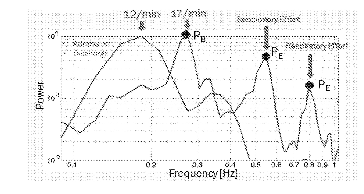
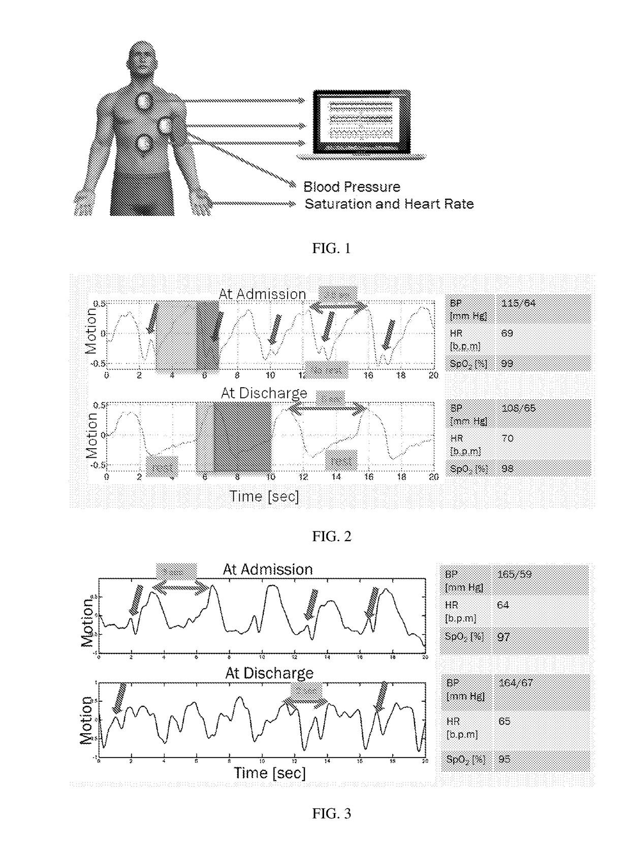
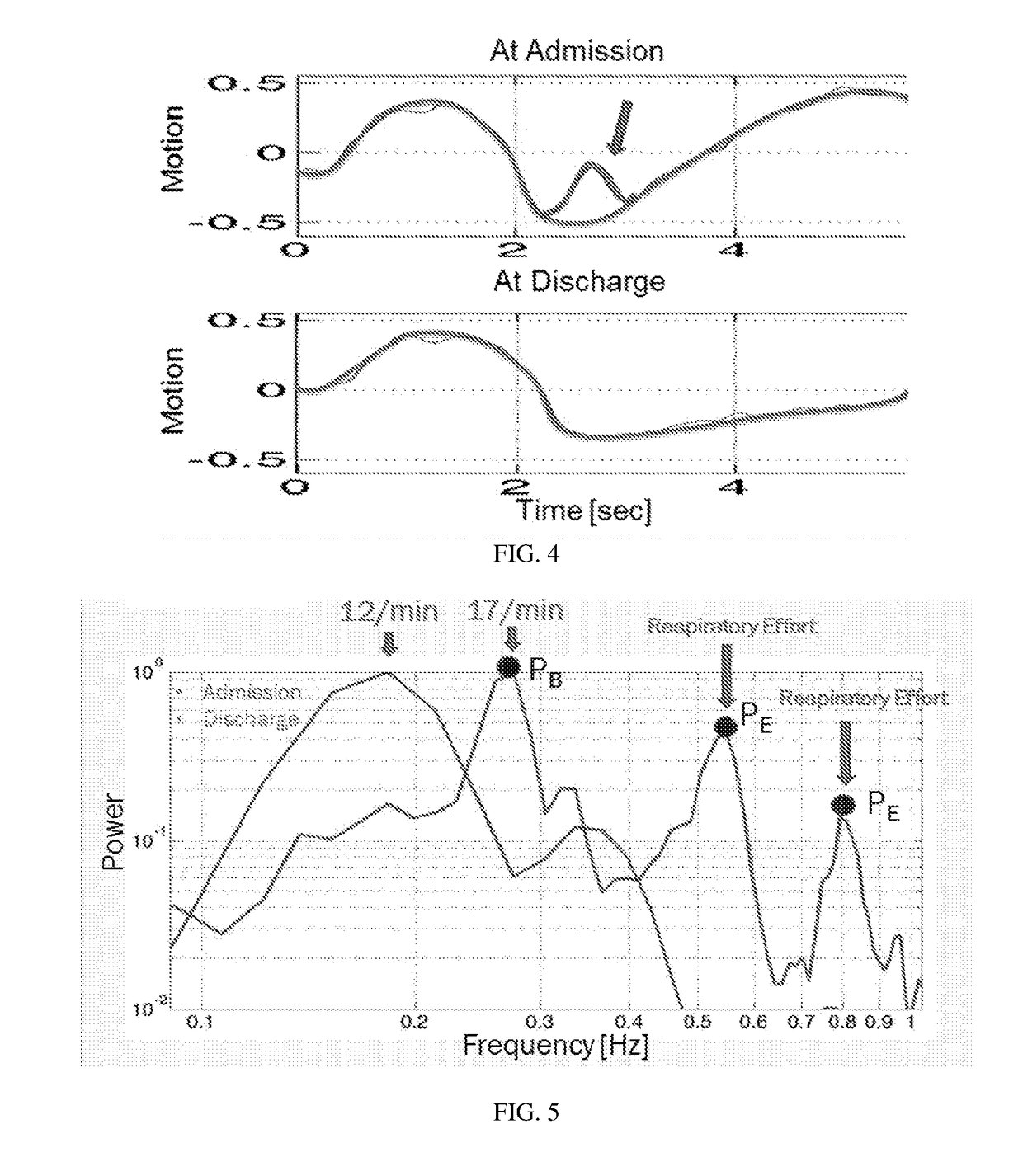
[0062]Reference is now made to FIG. 1, which illustrates a device for monitoring the respiratory dynamics for detecting and quantifying the development of signs for excessive respiratory work that is pathognomonic to HF. The system operates in accordance with a non-limiting embodiment of the present invention.

[0063]The device can continuously acquire and analyze the respiratory dynamics for a single sensor on the chest or the abdomen. In one embodiment, the sensor is an accelerometer. Other sensors, such as gyro-meters or gyroscope, which sense and quantify the motion of a single point in the space, can be used (all these types of sensors are referred to as a local acceleration sensor). Other accelerometers or alike may be used, such as on the abdomen. The sensors may be embodied in a patch, referred to as a patch and sensor unit.

[0064]The system includes[0065]the hardware for data amplification and filtration.[0066]the required data acquisition system and data storage for continuou...


PUM


Abstract

A method including sensing local accelerations or changes in sensor position, including orientation and displacement, with a local acceleration sensor mounted on a chest or abdomen of a patient, and calculating energy of polyphasic motions, based on sensed information of the local acceleration sensor and classifying severity of cardiac decompensation by calculating an excessive energy index (EEi) that compares excessive energy that appears in the polyphasic motions to energy required for inspiration at a basic respiratory rate.

Description

FIELD OF THE INVENTION[0001]The present invention is related to a method device and system for monitoring and quantifying the severity and progression of heart failure by novel objective and quantitative indices of the main symptom of heart failure patients, the dyspnea. The method is particularly useful, without limitation, for monitoring patients at home, for optimization of treatment of patients with heart failure, for determining the effectiveness of the treatment during electively hospitalization for stabilization of deteriorating cardiac decompensation, and for decision making before discharging patients from the hospital.BACKGROUND OF THE INVENTION[0002]Heart failure (HF) is a clinical syndrome resulting from structural or functional cardiac disorders that impair the ability of the heart to eject blood adequate for the needs of the body. The main manifestations in this syndrome are subjective symptoms of dyspnea (due to pulmonary congestion) and fatigue. These subjective symp...

Claims


Application Information

Patent Timeline
IPC IPC(8): G06F19/00A61B5/08
CPCG06F19/322G06F19/3431A61B2562/0219G06F19/345A61B5/0816G06F19/3406A61B5/1118A61B5/113A61B5/4866A61B5/6823A61B5/7264A61B5/7282A61B5/0022A61B5/0024A61B5/7275A61B2505/07A61B5/7253G16H40/63G16H10/60G16H50/30G16H50/20
Inventor LANDESBERG, AMIRZIBOLI, YAAKOVRISPLER, SHMUEL
Owner TECHNION RES & DEV FOUND LTD
Learn More