Interconnect for solid oxide fuel cell and method for manufacturing the same

a technology of solid oxide fuel cell and interconnection, which is applied in the direction of final product manufacturing, sustainable manufacturing/processing, electrochemical generators, etc., can solve the problems of significant deterioration of electrodes and electrolytes, affecting the performance of electrodes, and affecting the performance of electrolyte, etc., to achieve small voltage loss, simple structure, and maintain durability

Active Publication Date: 2017-03-16
SAMSUNG ELECTRO MECHANICS CO LTD
View PDF2 Cites 0 Cited by
  • Summary
  • Abstract
  • Description
  • Claims
  • Application Information

AI Technical Summary

Benefits of technology

[0016]The present invention has been made in an effort to provide an interconnect for a solid oxide fuel cell capable of maintaining durability against high-temperature heat generated from a flat type solid oxide fuel cell for a long time and thus having a very small voltage loss due to oxidation even with the use over a long-time period; having no sealing problem and no delaminating problem of a coating film due to a difference in coefficient of thermal expansion; being inexpensive; and having a simple structure, and a method for manufacturing the interconnect.
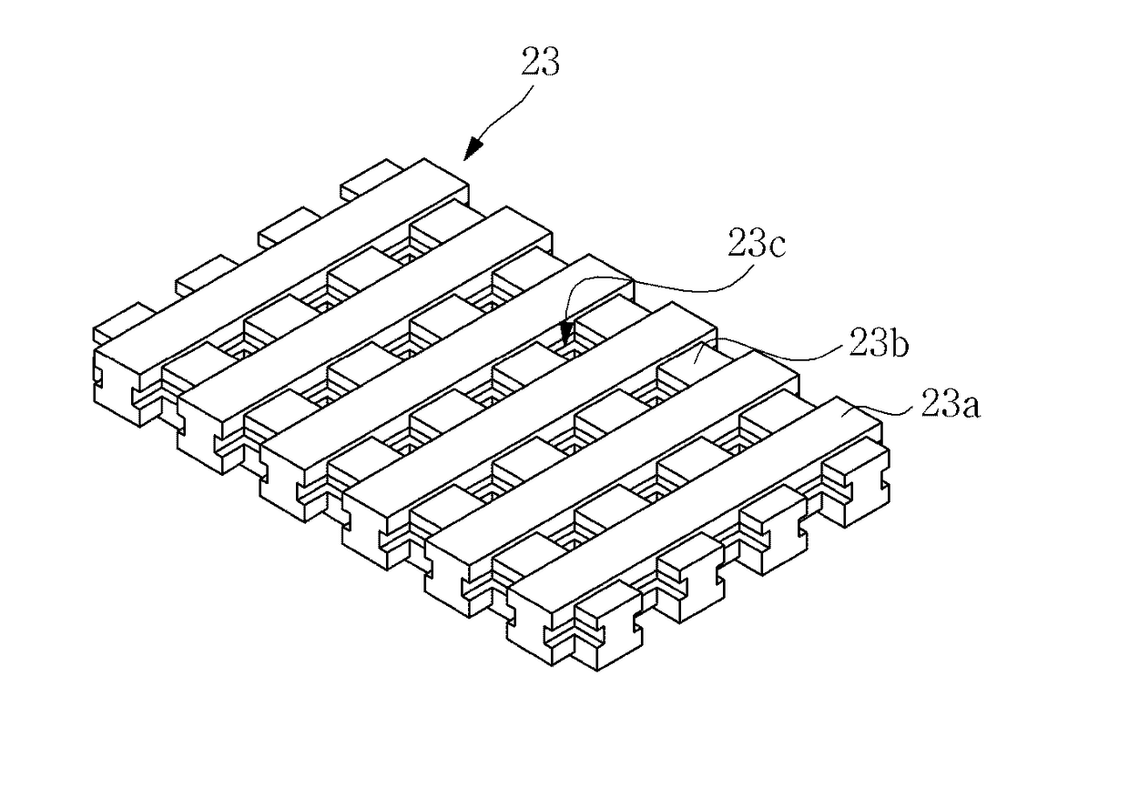
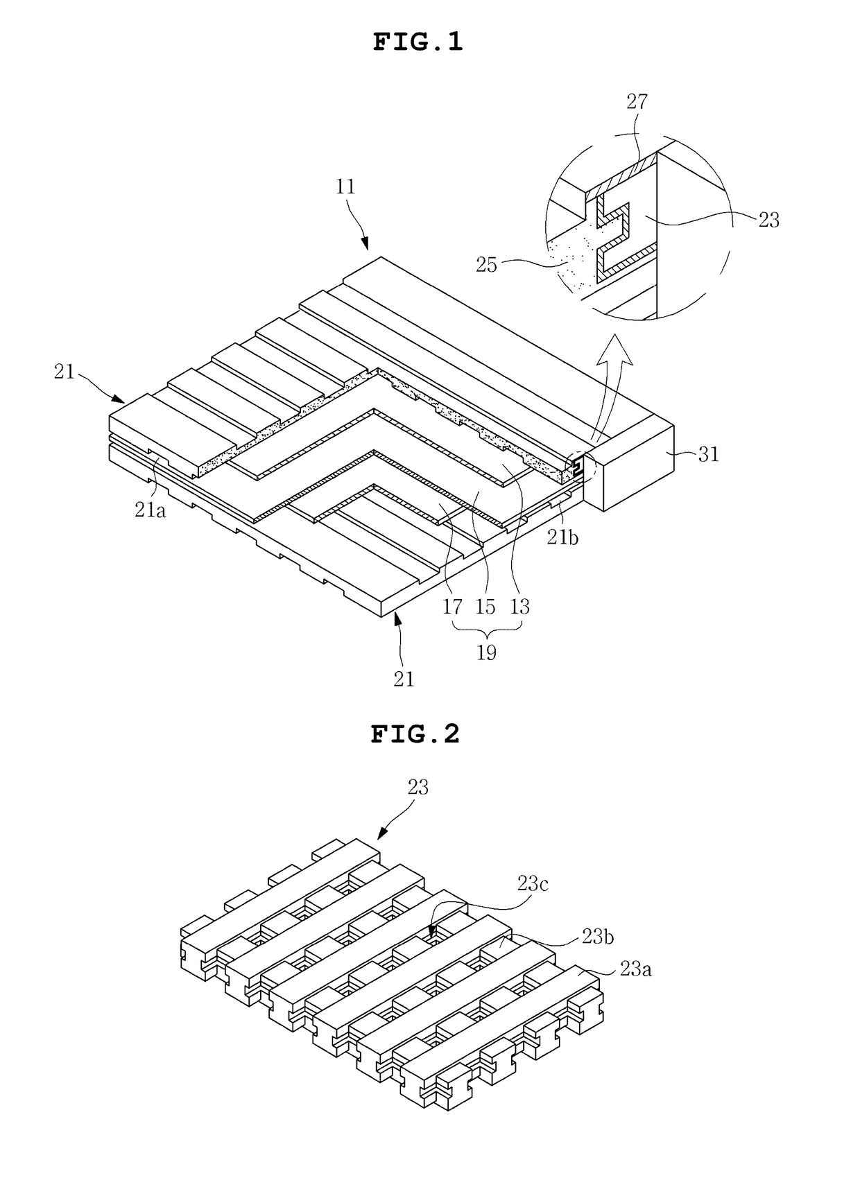
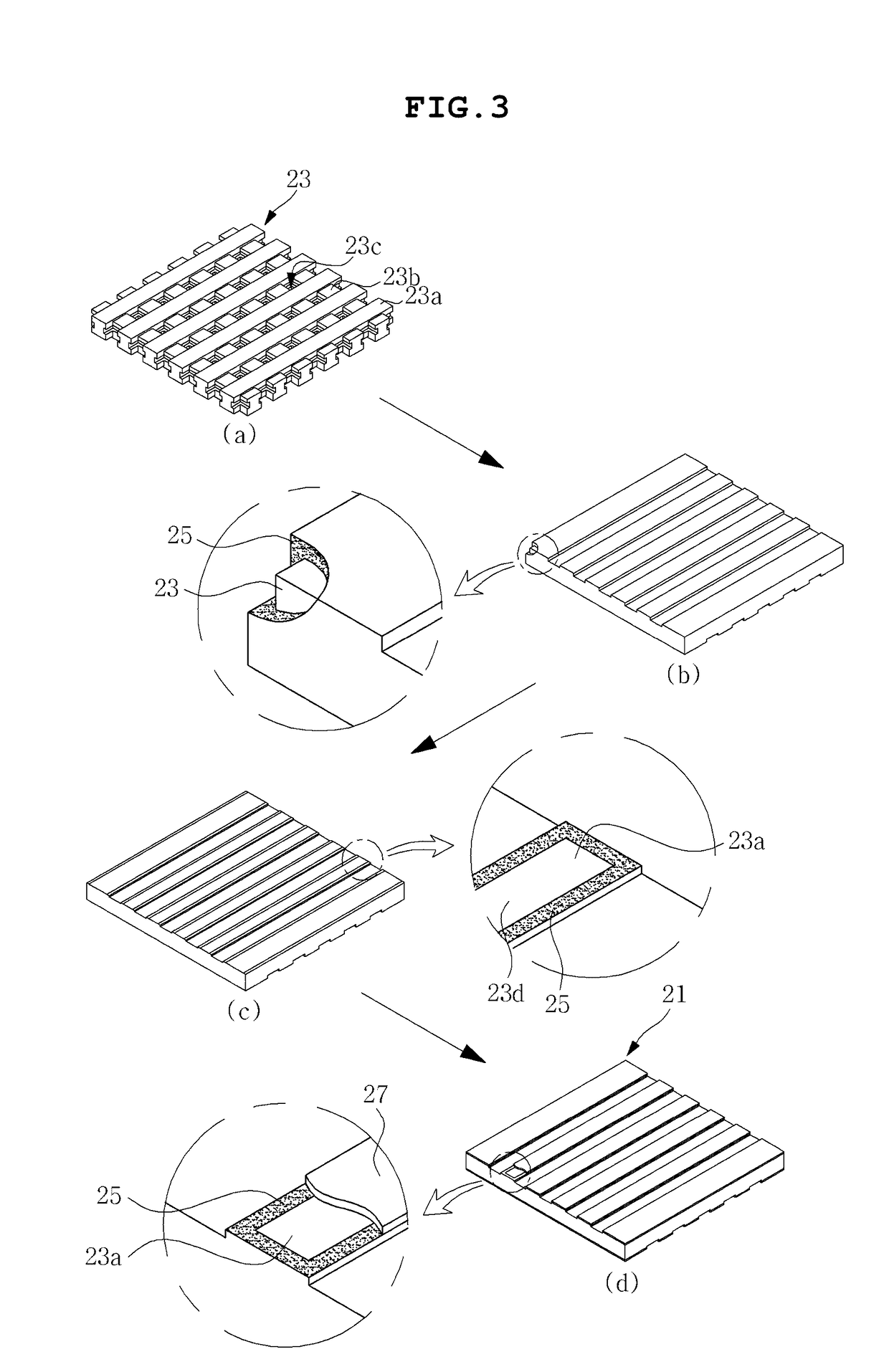
[0017]According to a preferred embodiment of the present invention, there is provided an interconnect for a solid oxide fuel cell, the interconnect including: a conductive core formed of an electroconductive material and taking the form of a lattice type plate; an oxidation-resistant insulating part receiving and wrapping the conductive core therein, to thereby prevent oxidation of the conductive core; and an oxidation-resistant conductive material layer coated on an exposed surface of the conductive core, which is exposed to an external environment by removing a portion of the oxidation-resistant insulating part, the oxidation-resistant conductive material layer being electrically connected with an electrode of an external fuel cell.
[0026]The interconnect may further include a middle layer laminated between the conductive core and the oxidation-resistant insulating part, to prevent delamination of the oxidation-resistant insulating part from the conductive core.

Problems solved by technology

Since oil currently widely used as an energy source is limited in reserves thereof, alternative energy substituting for the petroleum is a major national and social issue.
However, the existing interconnect is formed of a metal material, and thus may be easily oxidized in a high-temperature oxidation ambience to form an oxide film, and a chrome component inside the interconnect may move the electrodes or the electrolyte, which causes a secondary phase together with the components of the electrodes or the electrolyte.
The oxide film deteriorates electrical conductivity of the interconnect, resulting in decreasing electricity collecting efficiency, and in particular, the formation of the secondary phase due to the chrome component significantly deteriorates performances of the electrodes and the electrolyte.
However, the oxidation-resistant coating layer or the film layer has a difference in coefficient of thermal expansion from the inner interconnect, and thus causes delamination from the interconnect within a short time.
Moreover, the oxidation-resistant coating layer or the film layer also has a difference in coefficient of thermal expansion from a glass sealing agent on a lateral surface, which causes sealing problems.
For example, U.S. Pat. No. 8,173,328 (Interconnects for Solid Oxide Fuel Cells and Ferritic Stainless Steels Adapted for Use with Solid Oxide Fuel Cells) discloses that oxidation is prevented through surface treatment of a metal interconnect having holes and gas channels, but this technology cannot completely prevent high-temperature oxidation of a metal material and cannot solve the problem that the chrome component in the terrific stainless steel reacts with the components of the fuel cell, which deteriorates durability of the cell.

Method used


Image

  • Interconnect for solid oxide fuel cell and method for manufacturing the same
  • Interconnect for solid oxide fuel cell and method for manufacturing the same
  • Interconnect for solid oxide fuel cell and method for manufacturing the same

Examples


Embodiment Construction

[0039]The objects, features and advantages of the present invention will be more clearly understood from the following detailed description of the preferred embodiments taken in conjunction with the accompanying drawings. Throughout the accompanying drawings, the same reference numerals are used to designate the same or similar components, and redundant descriptions thereof are omitted. Further, in the following description, the terms “first”, “second”, “one side”, “the other side” and the like are used to differentiate a certain component from other components, but the configuration of such components should not be construed to be limited by the terms. Further, in the description of the present invention, when it is determined that the detailed description of the related art would obscure the gist of the present invention, the description thereof will be omitted.

[0040]Hereinafter, preferred embodiments of the present invention will be described in detail with reference to the attac...


PUM

PropertyMeasurementUnit
melting pointaaaaaaaaaa
reaction rateaaaaaaaaaa
temperatureaaaaaaaaaa

Abstract

Disclosed herein are an interconnect for a solid oxide fuel cell and a method for manufacturing the same, the interconnect including: a conductive core; an oxidation-resistant insulating part receiving therein; and an oxidation-resistant conductive material layer coated on an exposed surface of the conductive core, which is exposed to an external environment by removing a portion of the oxidation-resistant insulating part, so that the interconnect can maintain durability against high-temperature heat generated from a flat type solid oxide fuel cell for a long time and thus have a very small voltage loss due to oxidation even with the use over a long-time period; have no sealing problem and no delaminating problem of a coating film due to a difference in coefficient of thermal expansion; be inexpensive; and have a simple structure.

Description

CROSS REFERENCE TO RELATED APPLICATION[0001]This application is a Divisional Application of U.S. Ser. No. 13 / 845,026, filed Mar. 17, 2013, which claims the benefit of priority of Korean Patent Application No. 10-2012-0150564, filed Dec. 21, 2012. The subject matter of each is incorporated herein by reference in entirety.BACKGROUND OF THE INVENTION[0002]1. Technical Field[0003]The present invention relates to an interconnect for a solid oxide fuel cell and a method for manufacturing the same.[0004]2. Description of the Related Art[0005]Since oil currently widely used as an energy source is limited in reserves thereof, alternative energy substituting for the petroleum is a major national and social issue. For example, interests on electricity generation using solar heat, tides, and wind, or fuel cells, rather than fossil fuels have been growing.[0006]The above fuel cell generates electricity by using a reverse reaction of an electrolysis reaction of water, and applies technology of co...

Claims


Application Information

Patent Timeline
Patent Type & Authority Applications(United States)
IPC IPC(8): H01M8/0228H01M8/0206C04B37/02H01M8/0215
CPCH01M8/0228H01M8/0215H01M8/0206C04B37/021C04B2237/68C04B2237/068C04B2237/066C04B2237/62H01M2008/1293Y02P70/50Y02E60/50H01M8/02H01M8/12
Inventor KIM, SUNG HANCHUNG, JONG HOYOON, JONG SIKKOO, BON SEOK
Owner SAMSUNG ELECTRO MECHANICS CO LTD
Why Eureka
Try Eureka