Roller transfer application method and application device for hot-melt adhesive

a technology of hot-melt adhesive and application method, which is applied in the direction of adhesive processes, coatings, chemistry apparatuses and processes, etc., can solve the problems of temperature change or deterioration of hot-melt adhesive, and achieve no deterioration or generation of oily smoke, reduce the application amount of hot-melt adhesive, and improve the effect of work environmen

Active Publication Date: 2017-03-23
SUN TOOL CORP
View PDF7 Cites 8 Cited by
  • Summary
  • Abstract
  • Description
  • Claims
  • Application Information

AI Technical Summary

Benefits of technology

[0038]The present invention has an effect that is not disclosed in the inventions in Patent Literature 1, Patent Literature 2, and Patent Literature 3, and the effect of the present invention is of reducing an application amount of a hot-melt adhesive to a substrate by feeding the hot-melt adhesive in a thin film state to a protruding face of a pattern roller.
[0039]Further, the hot-melt adhesive is directly applied to the protruding face of the pattern roller. Consequently, when roller transfer application of the hot-melt adhesive is performed, a transfer roller and an adhesive storing portion do not exist. Accordingly, due to absence of a portion where the hot-melt adhesive is exposed and stays, there is no deterioration or generation of oily smoke by overheating of the hot-melt adhesive, and no dispersion of volatile components of the hot-melt adhesive. Consequently, the present invention has an effect of maintaining a favorable work environment by preventing contamination of surroundings of the device.
[0040]Moreover, it is possible to stop the feeding of the hot-melt adhesive from the coater head in the roller transfer application of the application area including only the recess face (the application face including the non-application zone) while applying the hot-melt adhesive in the thin film state only to the protruding face to thereby obtain the desired application face.

Problems solved by technology

Consequently, Patent Literature 1 has problems of mixing of dust and other impurities into the hot-melt adhesive to be applied to the substrate surface, and a temperature change or deterioration of the hot-melt adhesive.

Method used


Image

  • Roller transfer application method and application device for hot-melt adhesive
  • Roller transfer application method and application device for hot-melt adhesive
  • Roller transfer application method and application device for hot-melt adhesive

Examples


example 1

EFFECTIVE EXAMPLE 1

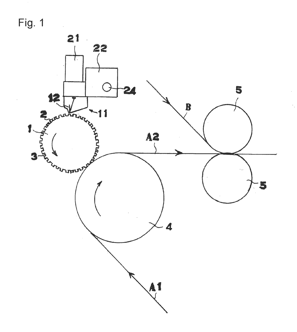
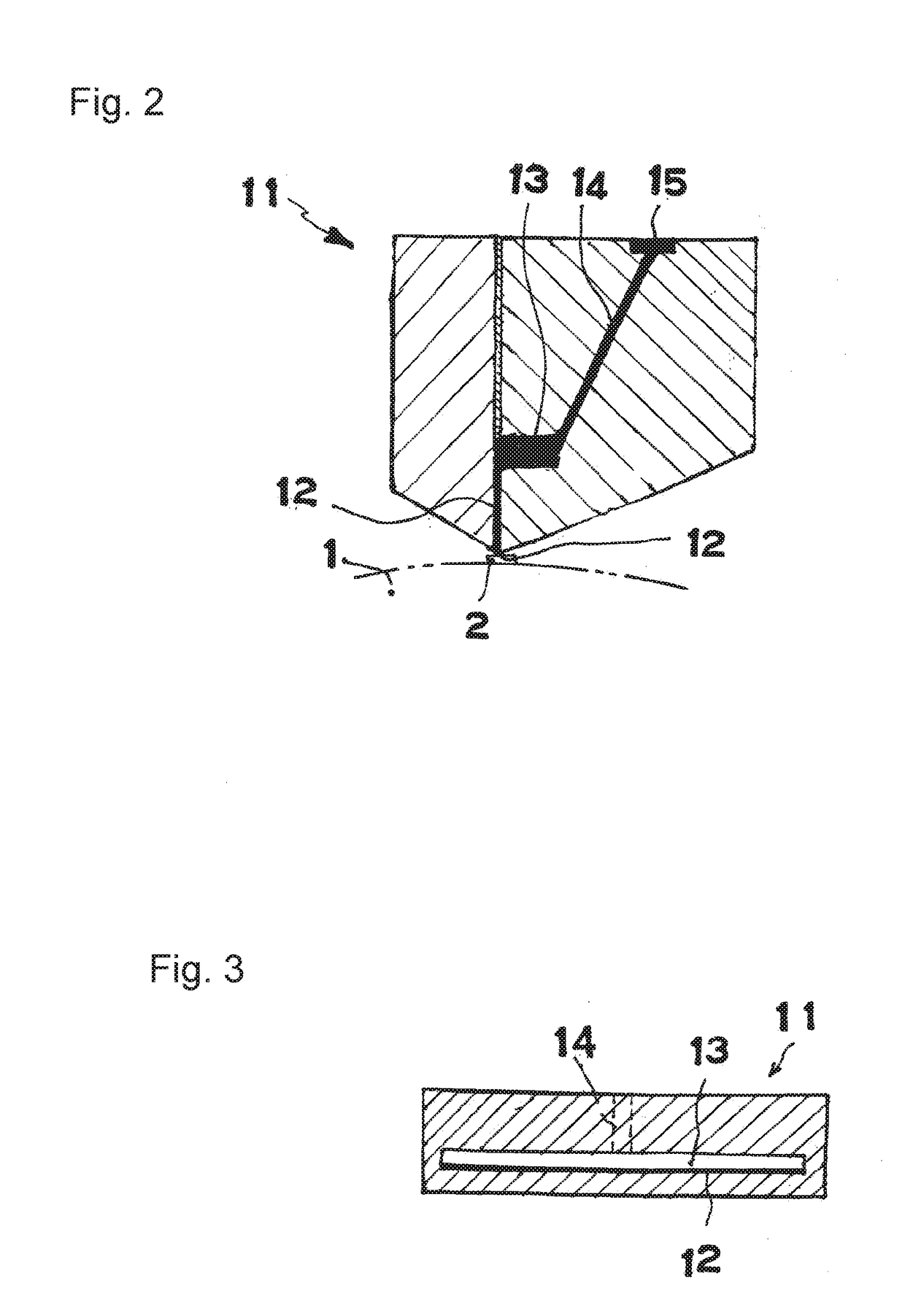
[0078]A protrusion and recess pattern: straight protrusions are arranged at constant intervals in a rotating direction and throughout the width in an axial direction.

[0079]The protrusions and recesses are arranged alternately in the rotating direction at intervals of 7.2 mm.

[0080]The width of each of the protrusions is 1 mm.

[0081]The height of each of the protrusions is 1 mm.

[0082]The application face on the application substrate: application straight lines having the width of 1 mm at intervals of 7.2 mm in a traveling direction of the application line.

[0083]The film thickness of the application face: 5μ to 3μ.

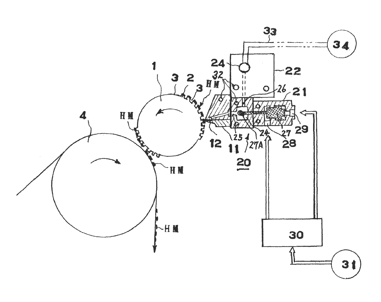
[0084]The opening of the slit (adhesive hole) of a bottom face of the slot die: a rectangle of 90 mm×0.2 mm.

[0085]The rotation speed of an adhesive feed pump of the hot-melt adhesive feeder: 19 rpm.

[0086]The clearance between the protrusion pattern surface of the pattern roller and the opening of the adhesive hole of the slot die: 0.015 to 0.05 mm.

[0087]The ...

example 2

EFFECTIVE EXAMPLE 2

[0089]The protrusion and recess pattern: the circular protrusions are arranged in the staggered arrangement.

[0090]The protrusions and the recesses are arranged alternately at intervals of 4 mm in the axial direction.

[0091]The protrusions and the recesses are arranged alternately at intervals of 5 mm in the rotating direction.

[0092]A diameter of each of the protrusions: 2 mm.

[0093]The height of each of the protrusions: 1 mm.

[0094]The application face on the application substrate: application straight lines having the width of 40 mm at intervals of 5 mm in the traveling direction of the application line.

[0095]The film thickness of the application face: 5μ to 30μ.

[0096]The opening of the slit (adhesive hole) of the bottom face of the slot die: a rectangle of 90 mm×0.2 mm.

[0097]The rotation speed of the adhesive feed pump of the hot-melt adhesive feeder: 10 rpm.

[0098]The clearance between the protrusion pattern surface of the pattern roller and the opening of the adhe...

reference example 1

[0103]In the first embodiment, when the rotation speed of the pattern roller was 38 rpm, a part of the hot-melt adhesive came in contact with the surfaces of the recesses, and the application failure was caused.


PUM

PropertyMeasurementUnit
thicknessaaaaaaaaaa
widthaaaaaaaaaa
widthaaaaaaaaaa

Abstract

In a roller transfer application method for a hot-melt adhesive, a coater head having a slot in a direction towards an axis center of a pattern roller is provided to face a pattern surface of the pattern roller; and by supplying the hot-melt adhesive, which is supplied from a hot-melt adhesive supply device, in a thin-film state to a pattern top surface of the pattern roller, thin-film hot-melt adhesive is thus only supplied to the top surfaces of protrusions of the pattern roller. By opening an on-off-type hot-melt adhesive supply control valve, which is attached to the coater head, at a timing that an adhesive opening (the slot) on the bottom surface of the coater head faces application zones on the pattern surface of the pattern roller, the hot-melt adhesive is supplied only to the top surfaces of the pattern roller protrusions.

Description

TECHNICAL FIELD[0001]The present invention relates to a roller transfer application method for a hot-melt adhesive and more specifically to a roller transfer application method for an adhesive, including applying an adhesive to a protrusion pattern surface of an application roller having a surface on which a protruding face of a desired pattern is formed, and transferring and applying the adhesive to a surface of a flexible application object such as paper or a plastic film which moves in contact with the application roll.BACKGROUND ART[0002]With regard to a roller transfer application method for an adhesive, there is known a roller transfer application method for a hot-melt adhesive, including means of applying a hot-melt adhesive fed from a hot-melt adhesive feeder to a protrusion pattern surface of a pattern roller in which a protrusion pattern is formed, means of transferring the hot-melt adhesive applied to protrusions of the pattern roller from the protrusion surface of the pa...

Claims


Application Information

Patent Timeline
Patent Type & Authority Applications(United States)
IPC IPC(8): B05D1/28B05D7/24C09J5/00B05D5/00
CPCB05D1/28B05D5/00C09J2201/61C09J5/00B05D7/24B32B37/1284B32B37/14B32B37/20B32B2037/1215B05D5/10B05C1/0808B05C1/0813B05C1/083B05C1/165C09J2301/304
Inventor HIDAKA, SHOJISAKAI, HISASHITARUMI, SEIKI
Owner SUN TOOL CORP
Why Eureka
Try Eureka