
System, method and apparatuses for identifying load volatility of a power customer and a tangible computer readable medium

a technology of load volatility and system, applied in the field of power grid technology, can solve the problems of no load volatility identification solution in the power industry, and cannot be used in load volatility identification

Active Publication Date: 2017-03-23
ACCENTURE GLOBAL SERVICES LTD
View PDF0 Cites 19 Cited by
  • Summary
  • Abstract
  • Description
  • Claims
  • Application Information

AI Technical Summary

Benefits of technology

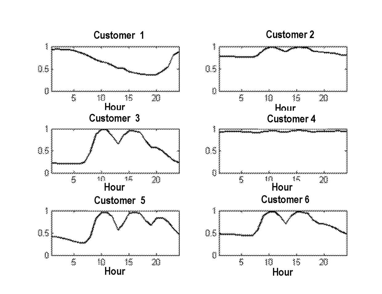
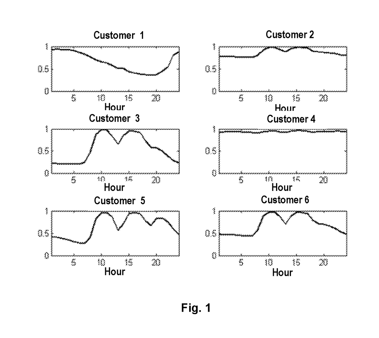
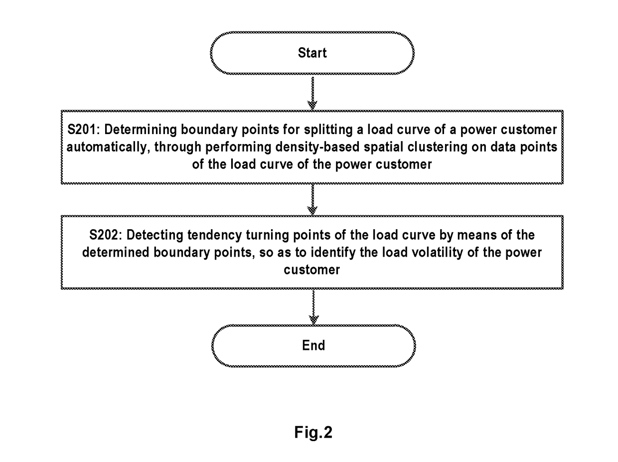
The present patent provides a system, method, and apparatus for identifying the load volatility of a power customer by automatically determining boundary points for splitting a load curve of the customer and detecting tendency turning points of the load curve using density-based spatial clustering. This approach allows for self-adapted auto-identification of load volatility, which can aid in optimizing power distribution networks and ensuring reliable power supply.

Problems solved by technology

The key problem of piecewise approximation is how to determine reasonable pre-specified boundaries of the split pieces.
Although these piecewise approximation based methods have been applied in hydrology, stock prediction, and aerospace, etc., they cannot be used in load volatility identification because these methods all need pre-specified threshold to control the error norm or number of pieces.
While the customers' volatilities are random and diversified, and one certain threshold can't meet all different kinds of volatilities and on the other hand, unlike the other application which care about error norm, the utilities care more about the load fluctuation trends.
Therefore, currently, there is no load volatility identification solution in the power industry yet.

Method used


Image

  • System, method and apparatuses for identifying load volatility of a power customer and a tangible computer readable medium
  • System, method and apparatuses for identifying load volatility of a power customer and a tangible computer readable medium
  • System, method and apparatuses for identifying load volatility of a power customer and a tangible computer readable medium

Examples


Embodiment Construction

[0037]Hereinafter, embodiments of the present disclosure will be described with reference to the accompanying drawings. In the following description, numerous specific details are set forth in order to provide a thorough understanding of the embodiments. However, it is apparent to the skilled in the art that implementation of the present disclosure may not have these details and the present disclosure is not limited to the particular embodiments as introduced herein. On the contrary, any arbitrary combination of the following features and elements may be considered to implement and practice the present disclosure, regardless of whether they involve different embodiments. Thus, the following aspects, features and embodiments are only for illustrative purposes, and should not be understood as elements or limitations of the appended claims, unless otherwise explicitly specified in the claims. Additionally, in some instances, well known methods and structures have not been described in ...


PUM


Abstract

The present disclosure relates to system, method and apparatuses for identifying load volatility of a power customary and a tangible computer readable medium therefor. In an embodiment of the present disclosure, the system comprises at least one processor; and at least one memory storing computer executable instructions. The at least one memory and the computer executable instructions are configured to, with the at least one processor, cause the system to determine boundary points for splitting a load curve of a power customer automatically, through performing density-based spatial clustering on data points of the load curve of the power customer; and detect tendency turning points of the load curve by means of the determined boundary points, so as to identify the load volatility of the power customer. With embodiments of the present disclosure, the boundary points for splitting the load curve may be determined automatically based on load data of each power customer instead of using a predetermined threshold and thus the load volatility of the load curve, which could provide a solution of self-adapted auto-identification for load volatility.

Description

TECHNICAL FIELD[0001]Embodiments of the present disclosure relate to the field of power grid technology and more particularly to system, method, and apparatuses for identifying load volatility of a power customer and a tangible computer readable medium.BACKGROUND[0002]Various industries have networks associated with them. One such industry is the utility industry that manages a power grid. The power grid may include one or all of the following: electricity generation, electric power transmission, and electricity distribution. Electricity may be generated using generating stations, such as a coal fire power plant, a nuclear power plant, etc. For efficiency purposes, the generated electrical power is stepped up to a very high voltage (such as, for example, 345K Volts) and transmitted over transmission lines. The transmission lines may transmit the power in long distances, such as across state lines or across international boundaries, until it reaches its wholesale customer, which may ...

Claims


Application Information

Patent Timeline
Patent Type & Authority Applications(United States)
IPC IPC(8): G06Q50/06G06F17/18
CPCG06F17/18G06Q50/06H02J3/003H02J2203/20Y02E60/00Y04S40/20Y04S10/50
Inventor HOU, FANGZHOU, QINLI, MING
Owner ACCENTURE GLOBAL SERVICES LTD
Learn More