Plastic-packaged stator and external rotor motor comprising the same

a stator and plastic-packaged technology, applied in the direction of mechanical energy handling, magnetic circuit rotating parts, magnetic circuit shape/form/construction, etc., can solve the problems of low structural integrity, prone to failure, and high cost of conventional stator production, so as to reduce waste produced during production process, save production cost, and high structural intensity

Active Publication Date: 2017-03-23
ZHONGSHAN BROAD OCEAN MOTOR MFG
View PDF3 Cites 6 Cited by
  • Summary
  • Abstract
  • Description
  • Claims
  • Application Information

AI Technical Summary

Benefits of technology

[0017]1. A plurality of lug bosses is circumferentially disposed at intervals on an outer wall surface of the sleeve base. An inner end of the iron core comprises slots. The tooth assemblies are circumferentially disposed on the outer wall surface of the sleeve base. The lug bosses are embedded in the slots. The plastic-packaged body integrates the sleeve base with the tooth assemblies. Each tooth assembly comprises an iron core comprising a plurality of laminated silicon steel sheets. The arrangement is simple. Waste produced during production process is reduced, thus production cost is saved. Meanwhile, the plastic-packaged stator is high in structural intensity, thus is reliable, and safe for long term use.
[0018]2. One side of the inner end of the iron core is provided with a bulge, and the other side is provided with a notch. The tooth assemblies are circumferentially disposed on the outer wall surface of the sleeve base. The bulge of one iron core is embedded in the notch of an adjacent iron core. The arrangement is simple. Therefore, on the one hand, the positioning and installation of tooth assemblies are easy, on the other hand, the connection between the tooth assemblies is reliable.
[0019]3. A bump is disposed between two adjacent lug bosses on the outer wall surface of the sleeve base. An axial extension length of the bump is smaller than an axial extension length of the lug bosses. The bump is used for positioning. The tooth assemblies are compressed on the outer wall surface of the sleeve base, and the installation is stopped when the tooth assemblies reach the bump. An open slot is formed between the bump and the lug bosses. During the installation, aluminum scraps are produced between the slot on the inner end of the tooth assemblies and the lug bosses on the outer wall surface of the sleeve base, and the aluminum scraps can be accommodated in the open slot instead of anywhere else, thus the aluminum scraps do not stand in the way of the installation of the tooth assemblies. The stator is well-designed, reliable, and features high quality.
[0020]4. A Hall plate assembly is disposed on the tooth assemblies. A socket is disposed on the Hall plate assembly. The plastic-packaged body is sleeved on the Hall plate assembly, and the socket protrudes from the plastic-packaged body. The arrangement is simple, thus facilitating the establishment of electrical connection between the plastic-packaged stator and the external power supply, or electrical connection between the plastic-packaged stator and the controller.
[0021]5. A plurality of supporting arms protrudes out of the sleeve base. Mounting holes are disposed on an external end of the supporting arms. The plastic-packaged body is sleeved on the supporting arms, with the mounting holes exposed. The arrangement is simple and the assembly is convenient. The structural intensity of the stator is improved.

Problems solved by technology

Conventional stator is costly and inefficient to produce, has low structural integrity, and is prone to failure during long-term use.

Method used


Image

  • Plastic-packaged stator and external rotor motor comprising the same
  • Plastic-packaged stator and external rotor motor comprising the same
  • Plastic-packaged stator and external rotor motor comprising the same

Examples


example 1

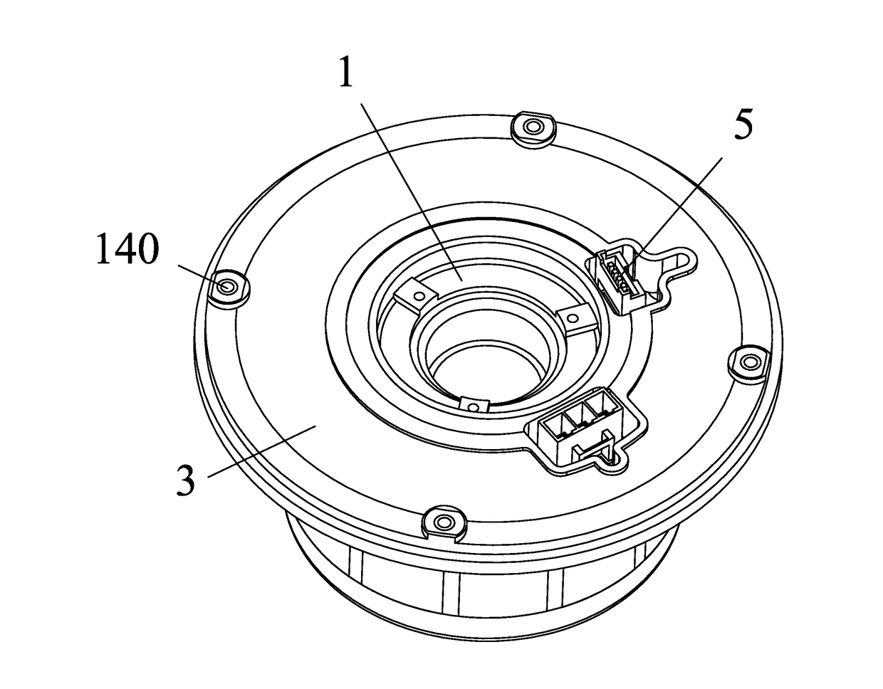
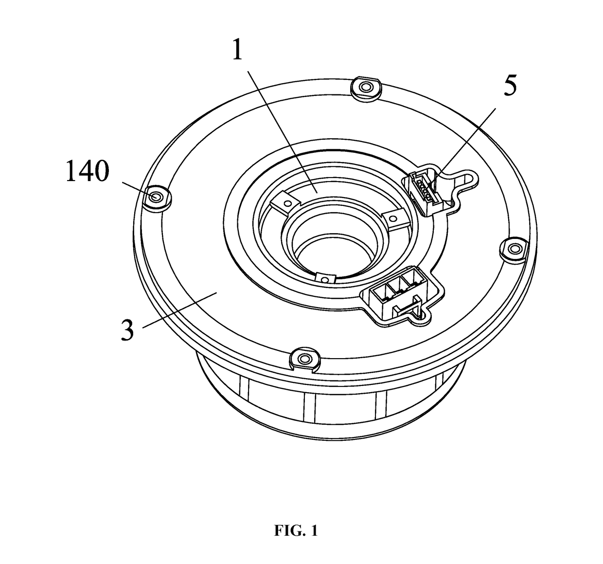
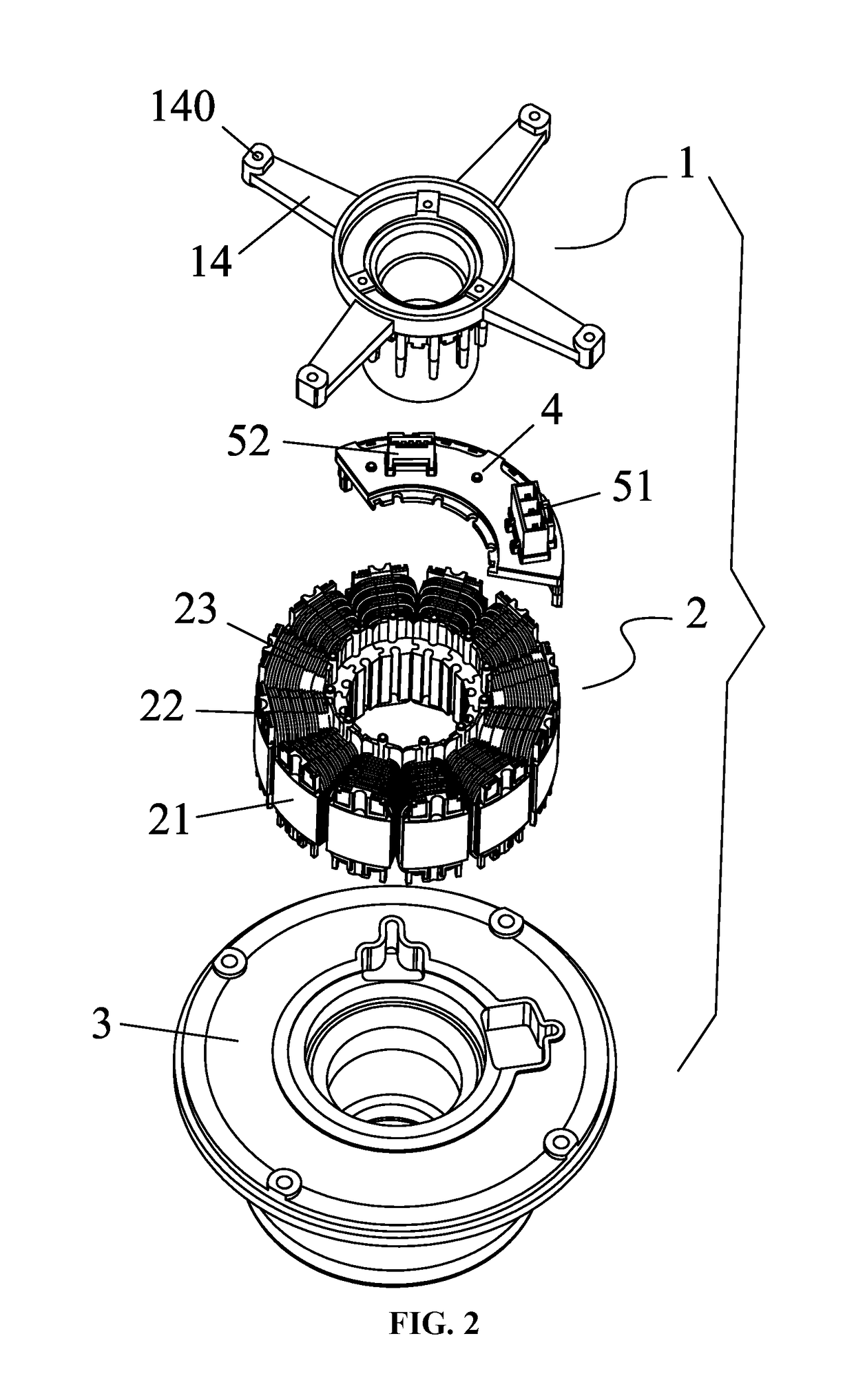
[0034]As shown in FIGS. 1-6, a plastic-packaged stator comprises a sleeve base 1, a plurality of tooth assemblies 2, and a plastic-packaged body 3. Each tooth assembly 2 comprises an iron core 21 comprising a plurality of laminated silicon steel sheets, a terminal insulator 22, and coil windings 23. The terminal insulator is disposed on one end of the iron core 21. The coil windings are coiled on the terminal insulator 22. A plurality of lug bosses 11 is circumferentially disposed at intervals on an outer wall surface of the sleeve base 1. An inner end of the iron core 21 comprises slots 211. The tooth assemblies 2 are circumferentially disposed on the outer wall surface of the sleeve base 1. The lug bosses 11 are embedded in the slots 211. The plastic-packaged body 3 integrates the sleeve base 1 with the tooth assemblies 2. One side of the inner end of the iron core 21 is provided with a bulge 212, and the other side is provided with a notch 213. The tooth assemblies 2 are circumfe...

example 2

[0035]As shown in FIGS. 1-10, an external rotor motor comprises a rotary shaft 6, a plastic-packaged stator, and an external rotor 7. The plastic-packaged stator comprises a sleeve base 1. Bearing housings 10 are disposed on two ends of the sleeve base 1. Each bearing housing 10 comprises a bearing 8. The rotary shaft 6 is disposed in the sleeve base 1, and two ends of the rotary shaft are supported by the bearing 8. The external rotor 7 is sleeved on the plastic-packaged stator. The external rotor 7 comprises a shell sleeve 71 and a plurality of permanent magnets 72. The permanent magnets are mounted on an inner wall surface of the shell sleeve 71. One end of the rotary shaft 6 protrudes out from the sleeve base 1 and is connected to the shell sleeve 71. The plastic-packaged stator comprises a plurality of tooth assemblies 2 and a plastic-packaged body 3. Each tooth assembly 2 comprises an iron core 21 comprising a plurality of laminated silicon steel sheets, a terminal insulator 2...


PUM


Abstract

A plastic-packaged stator includes a sleeve base, a plurality of tooth assemblies, and a plastic-packaged body. Each tooth assembly includes an iron core including a plurality of laminated silicon steel sheets, a terminal insulator, and coil windings. The terminal insulator is disposed on one end of the iron core. The coil windings are coiled on the terminal insulator. A plurality of lug bosses is circumferentially disposed at intervals on the outer wall surface of the sleeve base. An inner end of the iron core includes slots. The tooth assemblies are circumferentially disposed on the outer wall surface of the sleeve base. The lug bosses are embedded in the slots. The plastic-packaged body integrates the sleeve base with the tooth assemblies.

Description

CROSS-REFERENCE TO RELATED APPLICATIONS[0001]This application is a continuation-in-part of International Patent Application No. PCT / CN2015 / 090107 with an international filing date of Sep. 21, 2015, designating the United States, now pending, and further claims foreign priority benefits to Chinese Patent Application No. 201520264443.1 filed Apr. 28, 2015. The contents of all of the aforementioned applications, including any intervening amendments thereto, are incorporated herein by reference. Inquiries from the public to applicants or assignees concerning this document or the related applications should be directed to: Matthias Scholl P.C., Attn.: Dr. Matthias Scholl Esq., 245 First Street, 18th Floor, and Cambridge, Mass. 02142.BACKGROUND OF THE INVENTION[0002]Field of the Invention[0003]The invention relates to a plastic-packaged stator and an external rotor motor comprising the same.[0004]Description of the Related Art[0005]Conventional stator is costly and inefficient to produce,...

Claims


Application Information

Patent Timeline
Patent Type & Authority Applications(United States)
IPC IPC(8): H02K1/18H02K11/20H02K3/18H02K7/08H02K1/14H02K1/27
CPCH02K1/187H02K1/146H02K11/20H02K3/18H02K7/08H02K1/2786H02K1/148H02K3/522H02K15/12H02K11/215H02K11/33H02K1/2791H02K1/18H02K11/00
Inventor TANG, SONGFAJIAO, QINGMEI
Owner ZHONGSHAN BROAD OCEAN MOTOR MFG
Why Eureka
Try Eureka