Eureka AIR delivers breakthrough ideas for toughest innovation challenges, trusted by R&D personnel around the world.

Underwater 3D image reconstruction utilizing triple wavelength dispersion and camera system thereof

a 3d image and underwater camera technology, applied in underwater equipment, image data processing, waterborne vessels, etc., can solve the problems of underwater camera calibration that has not been addressed until recently, distortion in captured images, and underwater camera calibration remains a challenging problem

Inactive Publication Date: 2017-03-23
THE GOVERNORS OF THE UNIV OF ALBERTA
View PDF0 Cites 15 Cited by
  • Summary
  • Abstract
  • Description
  • Claims
  • Application Information

AI Technical Summary

Benefits of technology

The invention provides a method for estimating the housing parameters of an underwater camera by using triple wavelength dispersion without the need for a calibration target. This method requires no assumptions about the camera system or the refractive interface and can accurately reconstruct the 3D shape of objects using a single camera. The method is advantageous because it does not require a calibration object, such as a checkerboard pattern or a light box, and can find a unique solution of the camera housing parameters. The method is also more accurate and robust against noise than previous methods. The invention also includes a system for projecting a pattern of electromagnetic radiation and detecting the reflected radiation to compute the refractive normal and interface distance, which can be used to generate a 3D representation of the target object.

Problems solved by technology

Despite the remarkable success [18] for land-based camera systems, underwater camera calibration has not been addressed until recently.
As a result, the light that travels into the camera undergoes two refractions and its path is not a straight line, the result of which causes distortion in the captured images.
Therefore, calibrating underwater cameras remains a challenging problem in the computer vision area.
However, since the refraction effects are highly non-linear and depend on scene geometry, these methods usually produce errors.
Another requirement which is not practical is to require the refractive interface parallel to the image plane.
Other problems and limitations are also apparent from the existing work.
However, there is no demonstrated practical application disclosed in their paper.
One limitation is that it requires an Inertial Measurement Unit (IMU) to provide the vertical direction of each view.
Another limitation is that all the cameras must share the same interface.
One limitation is that its nonlinear optimization takes hours and the results of real data are not compared to the ground truth.
[10] develop an optimization procedure with the limitation that the refractive interface is parallel to the image plane.
Therefore, a checkerboard pattern is typically used which may not be practical when the cameras are deployed deep undersea.
One limitation is that it requires a heavy custom-built submersible light box which weighs over 60 lbs.
However, the results of real experiments are not evaluated against the ground truth.

Method used


Image

  • Underwater 3D image reconstruction utilizing triple wavelength dispersion and camera system thereof
  • Underwater 3D image reconstruction utilizing triple wavelength dispersion and camera system thereof
  • Underwater 3D image reconstruction utilizing triple wavelength dispersion and camera system thereof

Examples


Embodiment Construction

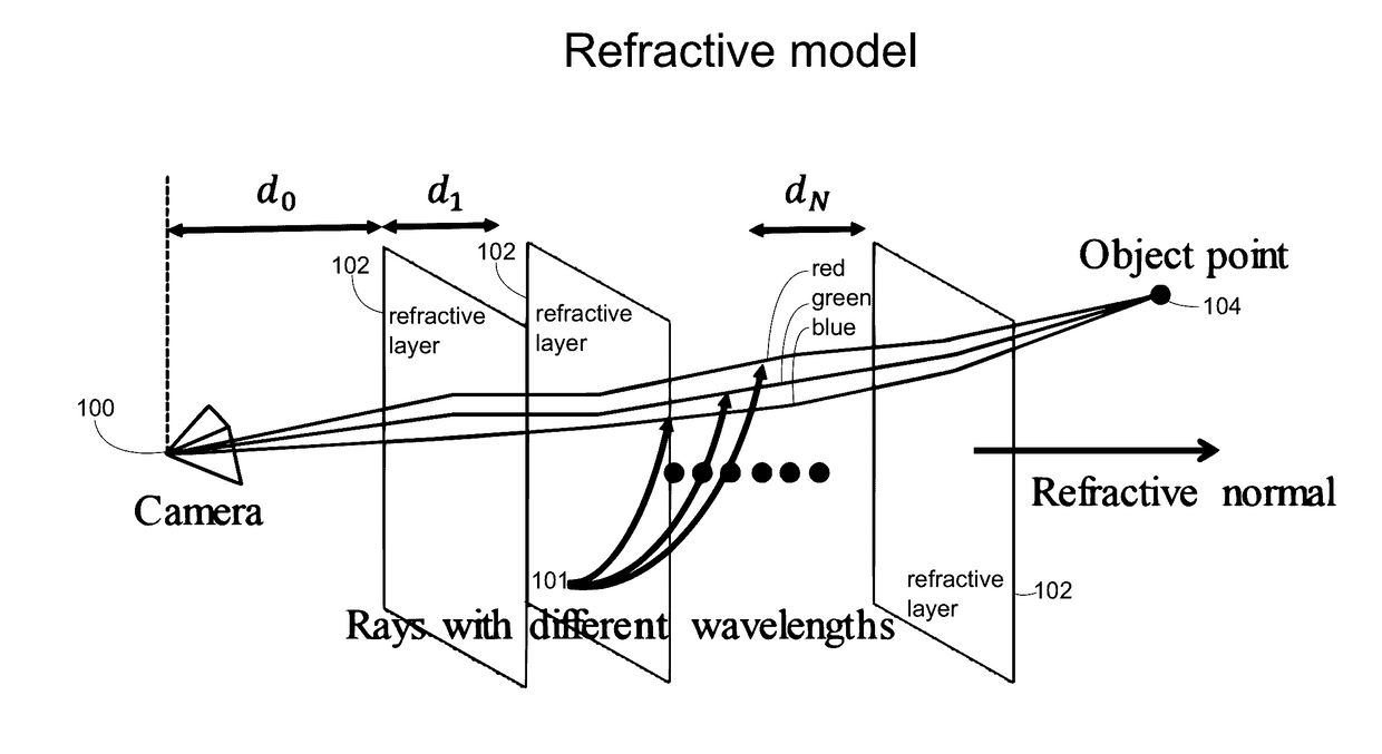
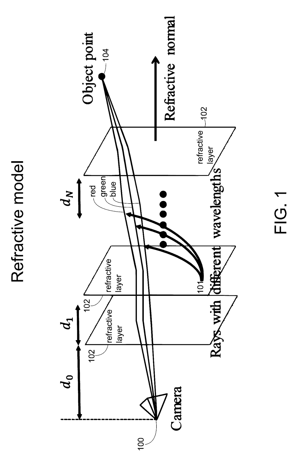
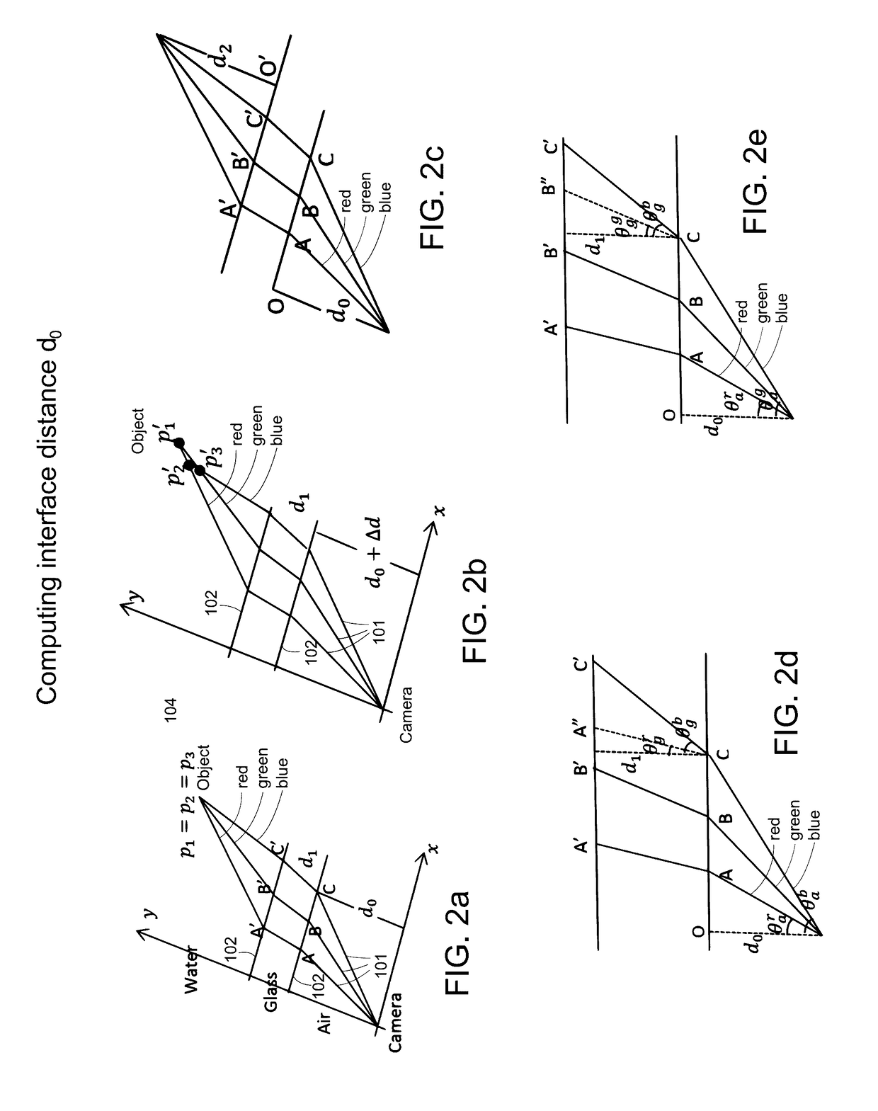
[0049]FIG. 1 shows the refraction model utilized according to an exemplary embodiment of the present invention. A pinhole perspective camera is viewing the object through multiple flat refractive layers where all layers are parallel to each other, which means that all layers have the same refractive interface normal n. The number of layers is N and each layer has a thickness of di. The distance from the camera center to the first refractive interface is denoted as the “interface distance”, d0. Assume that the object is able to emit three different wavelengths of light (red, green and blue), then the dispersion can be observed due to different refractive indices for different wavelengths. One goal in this embodiment is to compute both the refractive normal n and the interface distance d0.

[0050]This embodiment is directed at a specific refraction case which is a common and practical one. In particular, it is assumed that there are two refractions which are air→glass→water. This is a c...


PUM


Abstract

An underwater camera system includes a projector operable to project a pattern of electromagnetic radiation toward a target object. The electromagnetic radiation includes at least three different wavelengths. A sensor directed toward the target object receives reflected electromagnetic radiation from the target object and stores corresponding image data received from the sensor. One or more processors process the image data to compute a refractive normal according to a wavelength dispersion represented by differences in the image data, and to compute an interface distance corresponding to a distance from a center point of the sensor to a first refractive interface nearest the sensor according to the refractive normal. The processors generate a 3D representation of the target object by back projecting each pixel of the image data at the first, second, and third wavelengths in order to determine an object point location according to the refractive normal and interface distance.

Description

CROSS-REFERENCE TO RELATED APPLICATIONS[0001]This application claims the benefit of priority of U.S. Provisional Application No. 62 / 221,737 filed Sep. 22, 2015, which is incorporated herein by reference.BACKGROUND OF THE INVENTION[0002](1) Field of the Invention[0003]The invention pertains generally to underwater cameras. More specifically, the invention relates to a closed-form solution to single underwater camera calibration using triple wavelength dispersion and its application to 3D reconstruction of a target object.[0004](2) Description of the Related Art[0005]Computer vision has been a popular method to explore the underwater environment used by several groups of researchers such as biologists and geologists. It has many applications such as scientific exploration of the structure of the sea floor, and the monitoring of the undersea habitat. Hence, many researchers are interested in underwater computer vision. A fundamental and important topic in this area is underwater camera...

Claims


Application Information

Patent Timeline
Patent Type & Authority Applications(United States)
IPC IPC(8): H04N13/02B63G8/00B63G8/38
CPCH04N13/0275H04N13/0253H04N13/0207B63G2008/005B63G8/38B63G8/001B63G2008/004H04N13/0257G06T7/521G01B11/002G06T2207/10016G06T2207/10024G06T2207/10152
Inventor YANG, HERBERTCHEN, XIDA
Owner THE GOVERNORS OF THE UNIV OF ALBERTA
Why Eureka
Eureka Blog
Learn More