
Method and system for controlling charge and discharge of high powered energy storage systems

a high-power energy storage and charge and discharge technology, applied in the field of high-power energy storage systems, can solve the problems of not being adequately considered in the discussion of the potential of renewable energy sources, the and the lack of economic analysis of battery storage systems utilized for renewable energy sources. achieve the effect of optimizing energy flow and maximizing economic benefits

Inactive Publication Date: 2017-03-30
TEXAS TECH UNIV SYST
View PDF12 Cites 20 Cited by
  • Summary
  • Abstract
  • Description
  • Claims
  • Application Information

AI Technical Summary

Benefits of technology

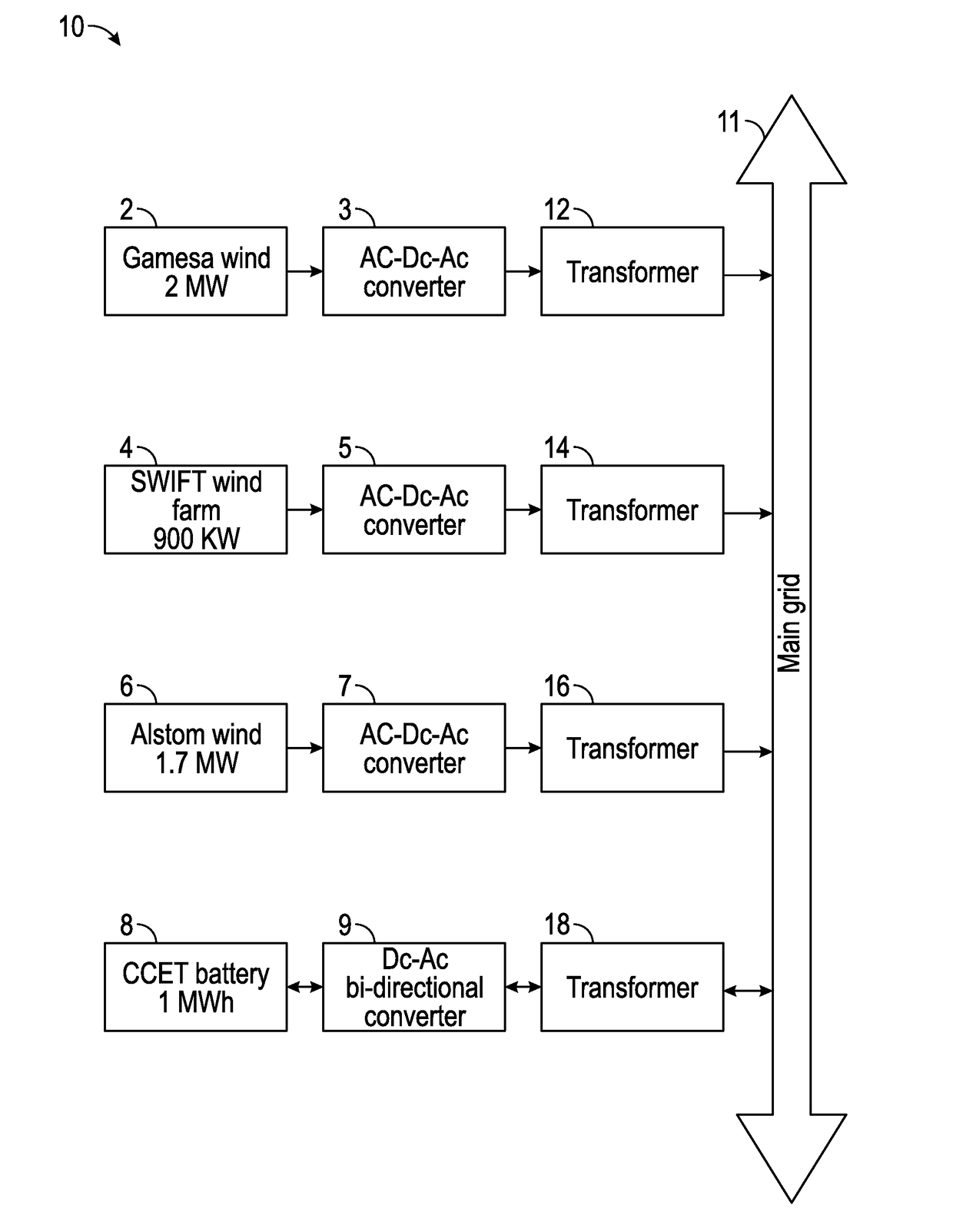
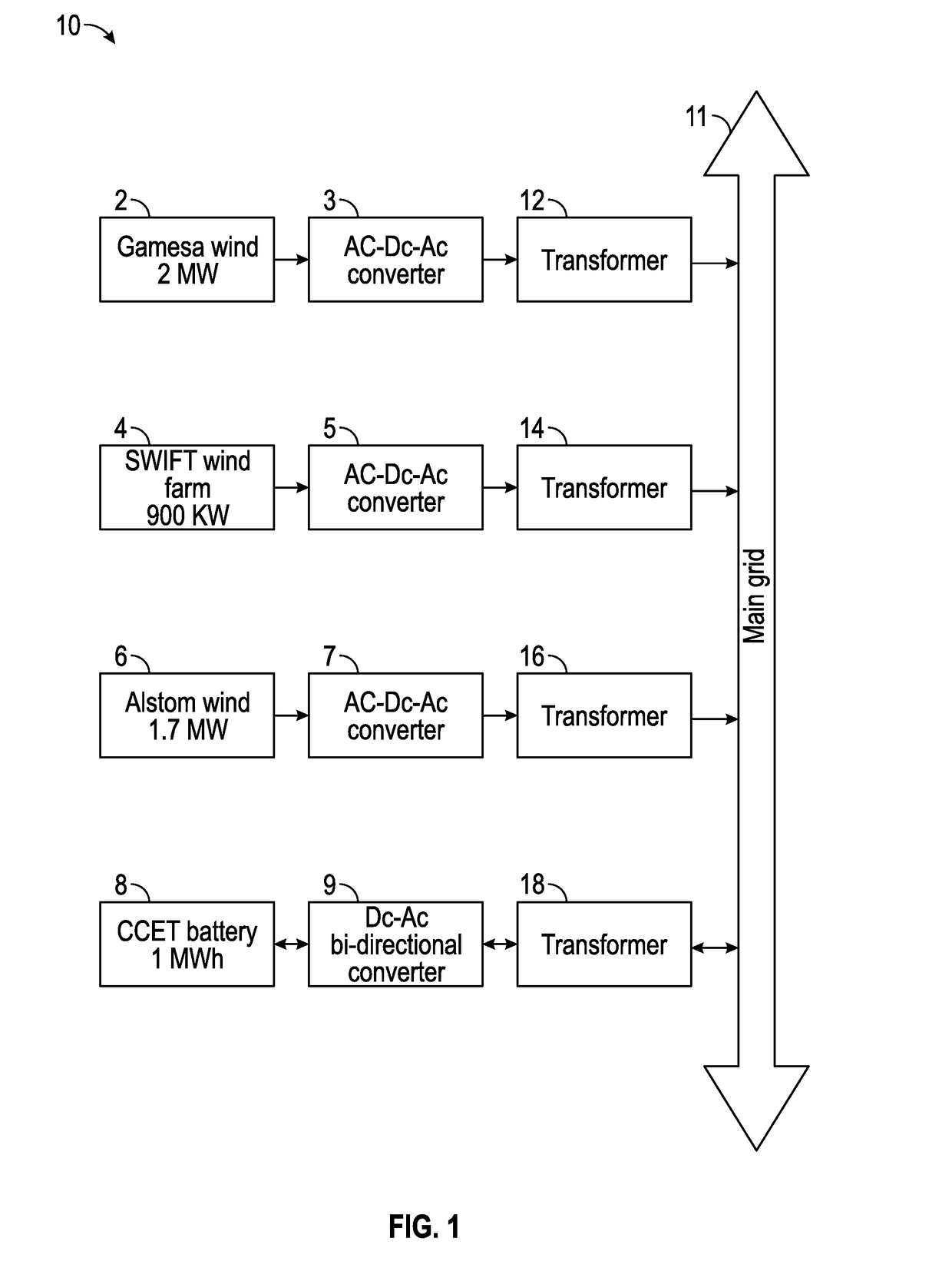
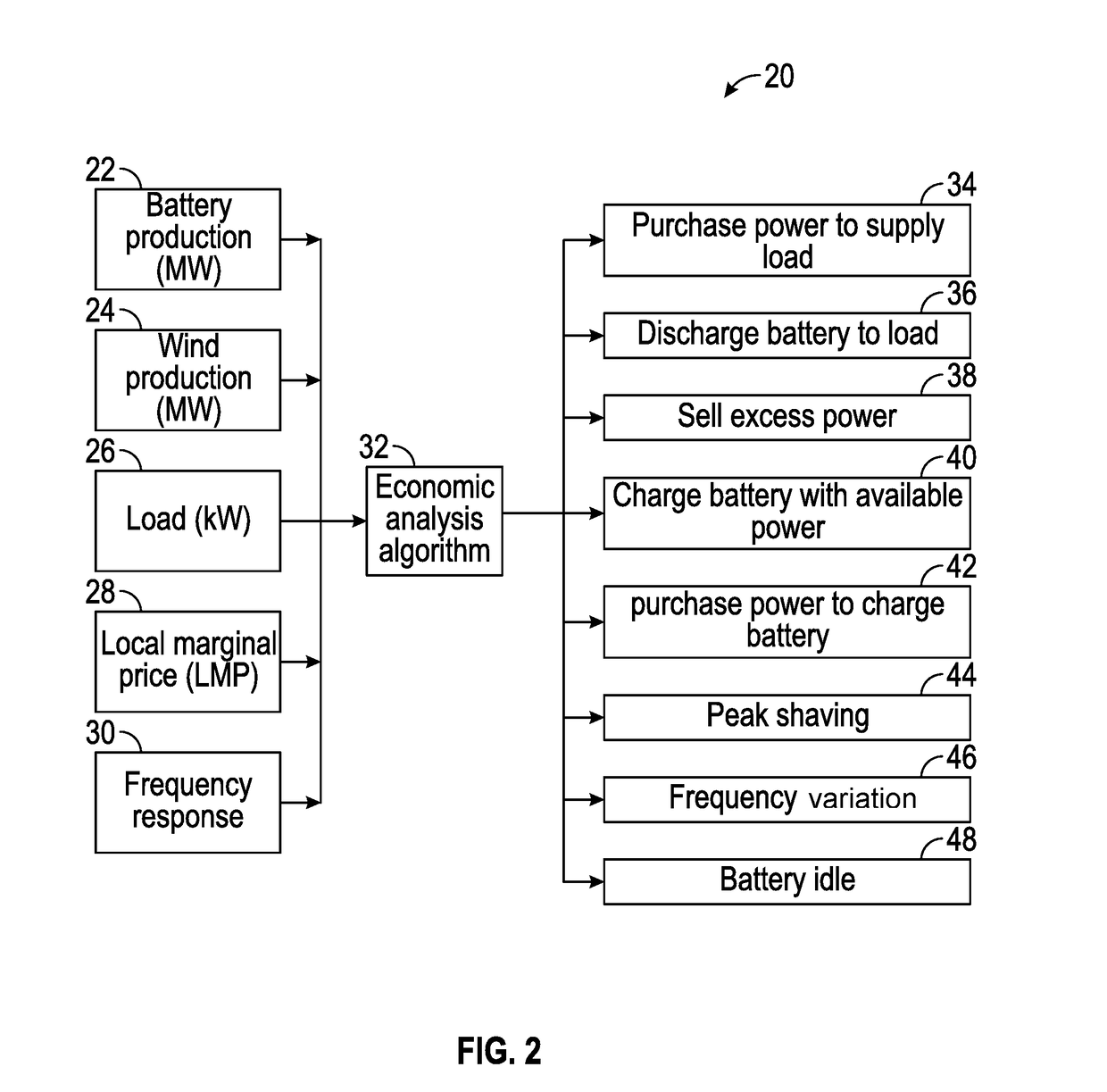
The patent describes a modeling framework for analyzing the economic feasibility of battery storage systems. This system can be used to optimize the energy flow between wind farms and utilities. The framework takes into account factors like the best time to charge and discharge the battery to maximize economic benefit. The method involves using a set of building blocks to perform the economic analysis, with a special focus on battery cycle life estimation. This analysis takes into account factors like the cost of energy to purchase and sell excess power, as well as the availability of renewable power in an economic way. Overall, the patent provides a technical solution for evaluating the economic viability of battery storage systems.

Problems solved by technology

Yet there has been little economic analysis of battery storage systems utilized for renewable energy sources.
The conclusion is that the main renewables like wind and the sun, face a major problem because of their intermittency (e.g., the wind doesn't always blow nor the sun always shine) and that this has not been adequately factored into discussions of their potential.
The benefits, however, are often difficult to quantify due to the complexity of different energy and storage applications.

Method used


Image

  • Method and system for controlling charge and discharge of high powered energy storage systems
  • Method and system for controlling charge and discharge of high powered energy storage systems
  • Method and system for controlling charge and discharge of high powered energy storage systems

Examples


Embodiment Construction

[0019]The particular values and configurations discussed in these non-limiting examples can be varied and are cited merely to illustrate at least one embodiment and are not intended to limit the scope thereof.

[0020]The embodiments will now be described more fully hereinafter with reference to the accompanying drawings, in which illustrative embodiments of the invention are shown. The embodiments disclosed herein can be embodied in many different forms and should not be construed as limited to the embodiments set forth herein; rather, these embodiments are provided so that this disclosure will be thorough and complete, and will fully convey the scope of the invention to those skilled in the art. Like numbers refer to identical, like or similar elements throughout, although such numbers may be referenced in the context of different embodiments. As used herein, the term “and / or” includes any and all combinations of one or more of the associated listed items.

[0021]The terminology used h...


PUM

PropertyMeasurementUnit
voltagesaaaaaaaaaa
energyaaaaaaaaaa
poweraaaaaaaaaa

Abstract

A modeling framework performs an economic analysis of a battery storage system to determine the economic feasibility with different business opportunities. The installed battery system can be utilized to optimize the energy flow between the wind farm and the utility. Several factors can be considered when performing the analysis, the most important being, how to determine the best optimal time to charge and discharge the battery to maximize economic benefit.

Description

CROSS-REFERENCE TO PROVISIONAL APPLICATION[0001]This nonprovisional patent application claims the benefit under 35 U.S.C. §19(e) of U.S. Provisional Patent Application Ser. No. 62 / 232,637 filed on Sep. 25, 2015, entitled “Method and System for Controlling Charge and Discharge of High Powered Energy Storage Systems”. U.S. Provisional Patent Application Ser. No. 62 / 232,637 is incorporated herein by reference in its entirety.TECHNICAL FIELD[0002]Embodiments are related to high powered energy storage systems. Embodiments also relate to methods and systems for controlling charge and discharge of high energy storage systems. Embodiments also relate to the economic analysis of high powered energy storage systems.BACKGROUND[0003]In the past several years, there has been tremendous increase in power production by renewable energy resources and the energy projection profiles indicate that the trend will continue for the next decade. Yet there has been little economic analysis of battery stora...

Claims


Application Information

Patent Timeline
Patent Type & Authority Applications(United States)
IPC IPC(8): G06Q50/06H01M10/42H02M5/42G05B13/04H02J3/38H01M10/46G06Q40/04
CPCG06Q50/06H01M10/46H01M10/425G06Q40/04G05B2219/49068H02J3/386H02M5/42H01M2220/10G05B13/042H02J3/008H02J3/32Y04S50/10H02J2300/28H02J3/381Y02E10/76Y04S10/50Y02E60/10Y02E70/30
Inventor SUBBURAJ, ANITHA SARAH
Owner TEXAS TECH UNIV SYST
Learn More