Traffic light driving control circuit

a control circuit and traffic light technology, applied in the field of driving integrated circuits, can solve the problems of increasing cost, difficulty in managing circuit elements, and only executing certain detections and controls by itself, and achieve the effects of less circuit elements, reduced element cost, and simplified managemen

Active Publication Date: 2017-03-30
LITE ON ELECTRONICS (GUANGZHOU) LTD +1
View PDF4 Cites 2 Cited by
  • Summary
  • Abstract
  • Description
  • Claims
  • Application Information

AI Technical Summary

Benefits of technology

[0005]The instant disclosure provides a drive integrated circuit (drive IC) for a controlling traffic light, such as a LED traffic light. Many circuits having different functions for driving or controlling the traffic light are all integrated in one single chip, and in this way less circuit elements are used. Using less circuit elements makes the element management become easier and decreases the element cost, and as a result the product quality is effectively improved. Moreover, using less circuit elements makes the traffic light have a less thick structure.

Problems solved by technology

Moreover, the original core circuit can only execute certain detections and controls by itself.
However, in this manner, the entire driving circuit of the traffic light is complex and has a big volume, which results in an increase of cost and a difficulty for the management of the circuit elements, and thus the quality of the traffic light suffers.

Method used


Image

  • Traffic light driving control circuit
  • Traffic light driving control circuit
  • Traffic light driving control circuit

Examples


first embodiment

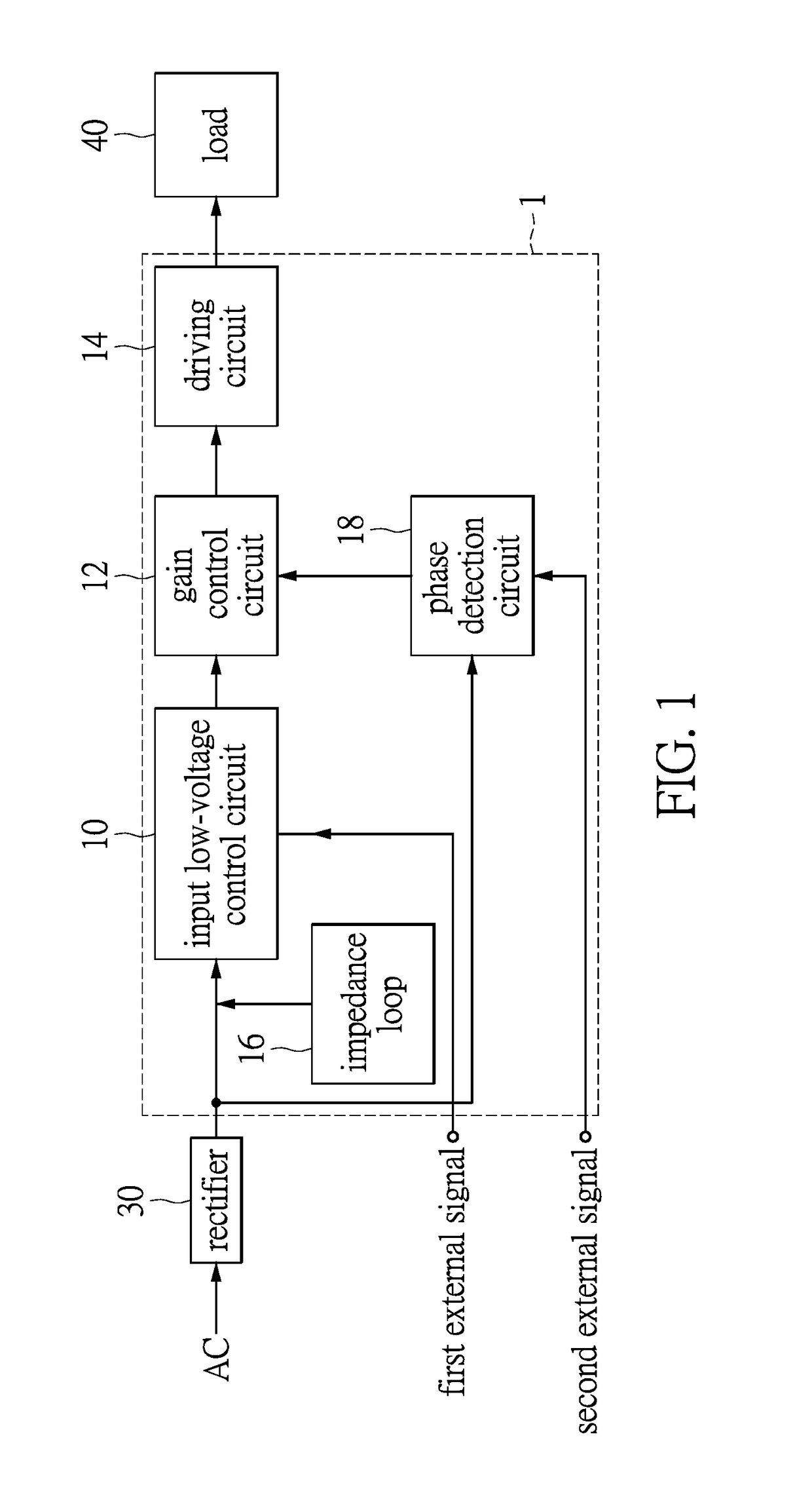
[0016]Referring to FIG. 1, FIG. 1 shows a block diagram of a drive IC for controlling a traffic light of the instant disclosure. As shown in FIG. 1, an input end of the drive IC 1 for controlling a traffic light is connected to a rectifier 30. The rectifier 30 receives and rectifies an AC power source and transmits the rectified current to the drive IC 1. An output end of the drive IC 1 is connected to a load 40, and the load 40 will be driven by the drive IC 1. The load 40 can be an LED illumination module, an LED light string, many lamp sets that are in serial, an LED lamp module or the like, but it is not limited herein. The rectifier 30 can be a full-bridge rectifier, a half-bridge rectifier, a center-tapped full-bridge rectifier or the like, but it is also not limited herein. Moreover, the AC power source can be a utility power. The drive integrated circuit having circuits having different functions for driving or controlling traffic lights which are all integrated in one singl...

second embodiment

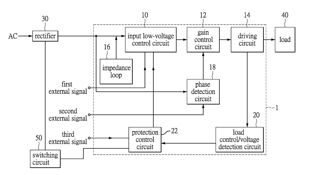
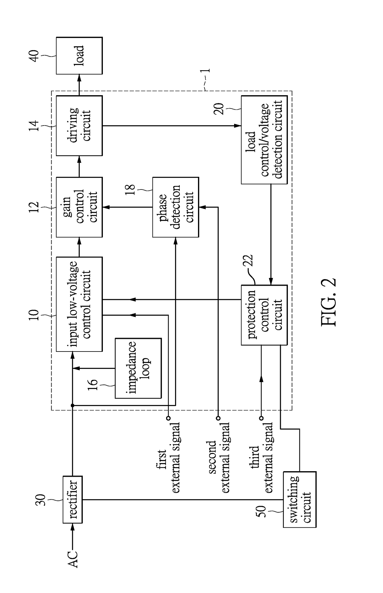
[0021]Referring to FIG. 2, FIG. 2 shows a block diagram of a drive IC for controlling a traffic light of the instant disclosure. The difference between the drive IC 1 shown in FIG. 1 and the drive IC 1 in this embodiment is that the drive IC 1 in this embodiment further comprises a load current / voltage detection circuit 20 and a protection control circuit 22. Moreover, a switching circuit 50 is connected to the drive IC 1, and the drive IC 1 further receives a third external signal. An input end of the load current / voltage detection circuit 20 is connected to the driving circuit 14, and an output end of the load current / voltage detection circuit 20 is connected to the protection control circuit 22. The load current / voltage detection circuit 20 detects the voltage and the current of the load 40. The protection control circuit 22 is connected to the input low-voltage control circuit 10 and the switching circuit 50, and receives the third external signal. The switching circuit 50 is co...


PUM


Abstract

Disclosed is a drive integrated circuit for controlling a traffic light. The drive IC comprises an input end and an output end, an input low-voltage control circuit, a gain control circuit, a driving circuit, an impedance loop and a phase detection circuit. The input low-voltage control circuit connects to the input end of the drive IC, and receives a first external signal. The gain control circuit connects to the input low-voltage control circuit. The driving circuit connects to the gain control circuit. The impedance loop connects to the input end to detect whether the traffic light is damaged. The phase detection circuit connects to the input end to detect a phase difference of the driving signal. By integrating circuits having different detection and control functions in one single chip, the cost of the drive IC decreases and the traffic light can have a less thick structure.

Description

BACKGROUND OF THE INVENTION[0001]1. Field of the Invention[0002]The instant disclosure relates to a drive integrated circuit (drive IC); in particular, to a drive IC having many circuits comprising different functions integrated for driving and controlling a traffic light.[0003]2. Description of Related Art[0004]For a traditional driving circuit of a traffic light, when different functions are required, new circuits need to be designed and they should be able to be applied to an original core circuit. Moreover, the original core circuit can only execute certain detections and controls by itself. There are some detection functions and some control functions that cannot be directly executed by the drive IC and thus new circuits need to be designed. The newly designed circuits should be able to be applied to the original core circuit, because it is the drive IC that drives them to execute their functions (e.g., a detection function or a control function). However, in this manner, the e...

Claims


Application Information

Patent Timeline
Patent Type & Authority Applications(United States)
IPC IPC(8): H05B33/08H05B44/00
CPCH05B33/0887H05B33/0842H05B33/0809H05B45/30H05B45/31H05B47/10G08G1/095H05B47/20
Inventor WANG, SHIH-CHANGNI, CHING-TSUNGWANG, CHIEN-LUNG
Owner LITE ON ELECTRONICS (GUANGZHOU) LTD
Why Eureka
Try Eureka