Disconnect switch for direct current interruption

a technology of disconnect switch and direct current, which is applied in the direction of emergency protective device, emergency protective circuit arrangement, electrical apparatus, etc., can solve the problems of unavoidable power loss at the semiconductor, unavoidable performance loss, and mechanical switching contact wear down very quickly

Active Publication Date: 2017-04-06
ELLENBERGER & POENSGEN GMBH
View PDF10 Cites 9 Cited by
  • Summary
  • Abstract
  • Description
  • Claims
  • Application Information

AI Technical Summary

Benefits of technology

[0013]The semiconductor electronics of the circuit breaker according to the invention can, for example, have no additional power source and is therefore current-blocking, i.e. high-ohmic and thus virtually without current or voltage when the mechanical switch is closed. Since in closed mechanical switching contacts of the or of each circuit breaker of the circuit breaker arrangement no current flows over the semiconductor electronics, and therefore in particular no voltage drop occurs on the or on each semiconductor switch, the semiconductor circuit produces no performance losses when the switching contacts of the circuit breaker arrangement are closed. Rather, the semiconductor electronics receives the energy necessary for its operation from the disconnecting device itself. To this end, the energy of an arc formed during opening of the switching contacts of the or of each circuit breaker of the circuit breaker arrangement is used. In this regard, suitably a control input of the semiconductor electronics or of the semiconductor switch is interconnected such with the or with each circuit breaker that when opening switching contacts of the circuit breaker arrangement, the arc voltage switches the semiconductor electronics parallel thereto in a current-conducting, i.e. low-impedance and thus energized manner.
[0014]Once the semiconductor electronics is switched slightly current-conducting, the arc current begins to commutate from the circuit breaker or from the switching contacts of said breaker to the semiconductor electronics. Because in an advantageous embodiment the circuit breaker arrangement of the disconnecting device comprises at least two circuit breakers, which are, or whose switching contacts are, connected in series, and at least one circuit breaker of the circuit breaker arrangement is connected in series with the semiconductor electronics, in the event of the triggering of the circuit breaker arrangement, a galvanic isolation of the load from the DC power source is achieved, and thus, by opening this hybrid circuit breaker, complete galvanic direct current interruption.

Problems solved by technology

It is, however, a disadvantage that such mechanical switching contacts wear down very quickly due to the arc formed during contact opening, or that an additional effort is required to enclose and cool the arc, which is usually done by a corresponding mechanical switch with an arcing chamber.
If in contrast powerful semiconductor switches are used for load separation, then even during normal operation unavoidable power losses occur at the semiconductors.
In addition, with such power semiconductors, galvanic isolation and thus also reliable personal protection are not ensured.
Due to the electrical conductivity of the semiconductor circuit in the event of an arc, a comparatively low-ohmic current path is connected in parallel thereto, resulting in a comparatively early extinction of the arc and thus a comparatively low load of the disconnecting device or the interruption unit.

Method used


Image

  • Disconnect switch for direct current interruption
  • Disconnect switch for direct current interruption
  • Disconnect switch for direct current interruption

Examples


Embodiment Construction

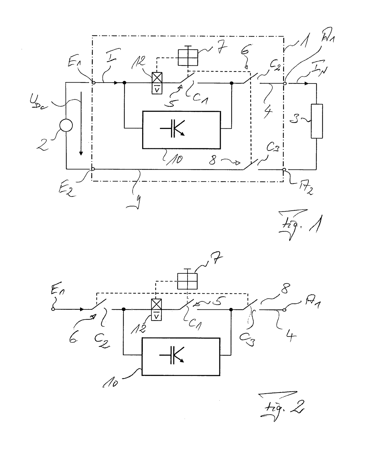
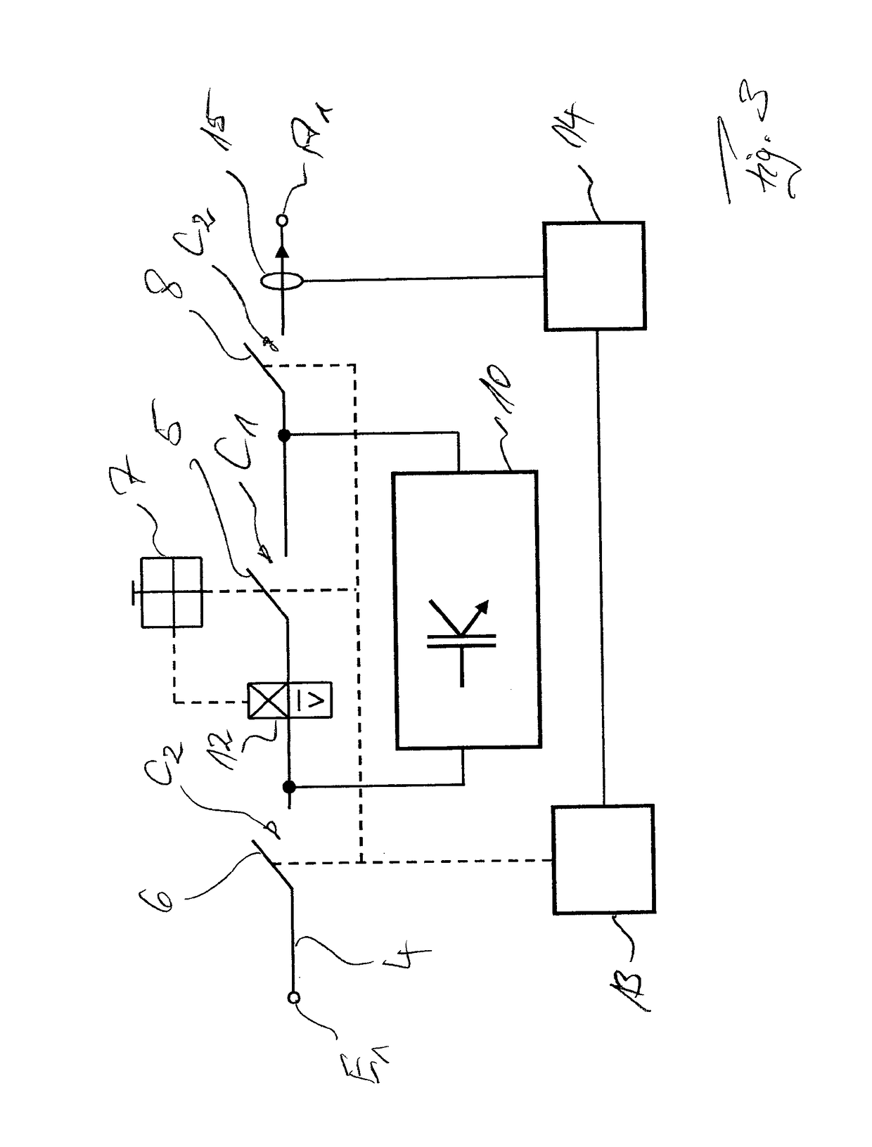
[0023]FIG. 1 schematically shows a disconnecting device 1 which is connected in the embodiment between a DC voltage source 2 for generating a DC voltage UDC and a direct current IN as well as a load 3. In the main current path or positive path 4 representing the positive terminal, the disconnecting device 1 comprises a circuit breaker arrangement in the form of a series circuit of two magnetic, in particular hydraulic-magnetic, circuit breakers 5, 6, whose switching contacts coupled to a switching mechanism 7 are designated CI and C2. Another circuit breaker 8 or switching contact C3 is switched to the return current or negative path (return line) 9 of the disconnecting device 1 and is also coupled to the switching mechanism 7.

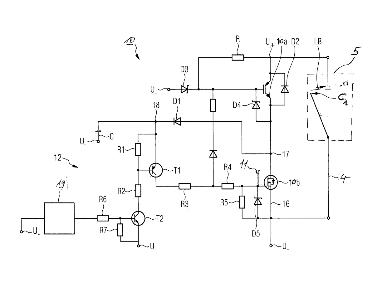
[0024]A semiconductor electronics 10 is connected in parallel to one of the circuit breakers 5, 6, 8, here, circuit breaker 5 or its switching contact C1. The circuit breakers 5, 6, 8 and the semiconductor electronics 10 form a self-sufficient hybrid circuit b...


PUM


Abstract

A disconnecting device for interrupting the direct current between a direct current source, in particular in the direct voltage range between 300VDc and / or in the nominal current range between 4 A and 250 A, and a load. The device has at least one protection switch with a protection switch arrangement having a magnetic trigger, and has semiconductor electronics which are connected in parallel to the at least one protection switch and which block the current when the protection switch arrangement is in a current-conducting state and which conducts current at least temporarily when the protection switch arrangement is triggered. A current, in particular an electric arc current generated as a result of an electric arc, is switched, when the protection switch arrangement is triggered, from the at least one protection switch to the semiconductor electronics.

Description

[0001]This nonprovisional application is a continuation of International Application No. PCT / EP2015 / 000576, which was filed on Mar. 16, 2015, and which claims priority to German Patent Application No. 10 2014 008 706.9, which was filed in Germany on Jun. 18, 2014, and which are both herein incorporated by reference.BACKGROUND OF THE INVENTION[0002]Field of the Invention[0003]The invention relates to a disconnecting device for direct current interruption between a direct current power source and an electrical device or a load. A direct current (DC) in this event can be understood to be a nominal current range between 4 ADC and 250 ADC in a DC voltage range between 300VDC and 1500VDC.[0004]Description of the Background Art[0005]Since such a DC voltage source, for example, of a photovoltaic system, as determined by the system on the one hand permanently provides an operating current and an operating voltage in the range between 180V (DC) and 1500V (DC), and on the other hand—for exampl...

Claims


Application Information

Patent Timeline
Patent Type & Authority Applications(United States)
IPC IPC(8): H02H3/087
CPCH02H3/087H01H9/542H01H9/548H01H71/1009H01H2071/124
Inventor GERDINAND, FRANKMECKLER, PETERMIKLIS, MARKUSNAUMANN, MICHAELSTROBL, CHRISTIAN
Owner ELLENBERGER & POENSGEN GMBH
Why Eureka
Try Eureka