Contained Growing Space and Environmental Control System

Active Publication Date: 2017-04-13
HARVEST AIR LLC
View PDF21 Cites 9 Cited by
  • Summary
  • Abstract
  • Description
  • Claims
  • Application Information

AI Technical Summary

Benefits of technology

[0009]In yet another embodiment, a method for treating air within a growing space of a closed agricultural system includes the following steps. Air is recirculated from a contained growing space through an air handling system having at least one energy wheel to reduce the energy content of the recirculating air. The recirculating air exiting the energy wheel(s)

Problems solved by technology

Lighting can cause excessive heat and high humidity, especially free water on the plant foliage, promotes the development of foliar diseases, such as tomato blight, gray mold, and mildews in various crops.
Su

Method used


Image

  • Contained Growing Space and Environmental Control System
  • Contained Growing Space and Environmental Control System
  • Contained Growing Space and Environmental Control System

Examples


Example

EXAMPLE 1

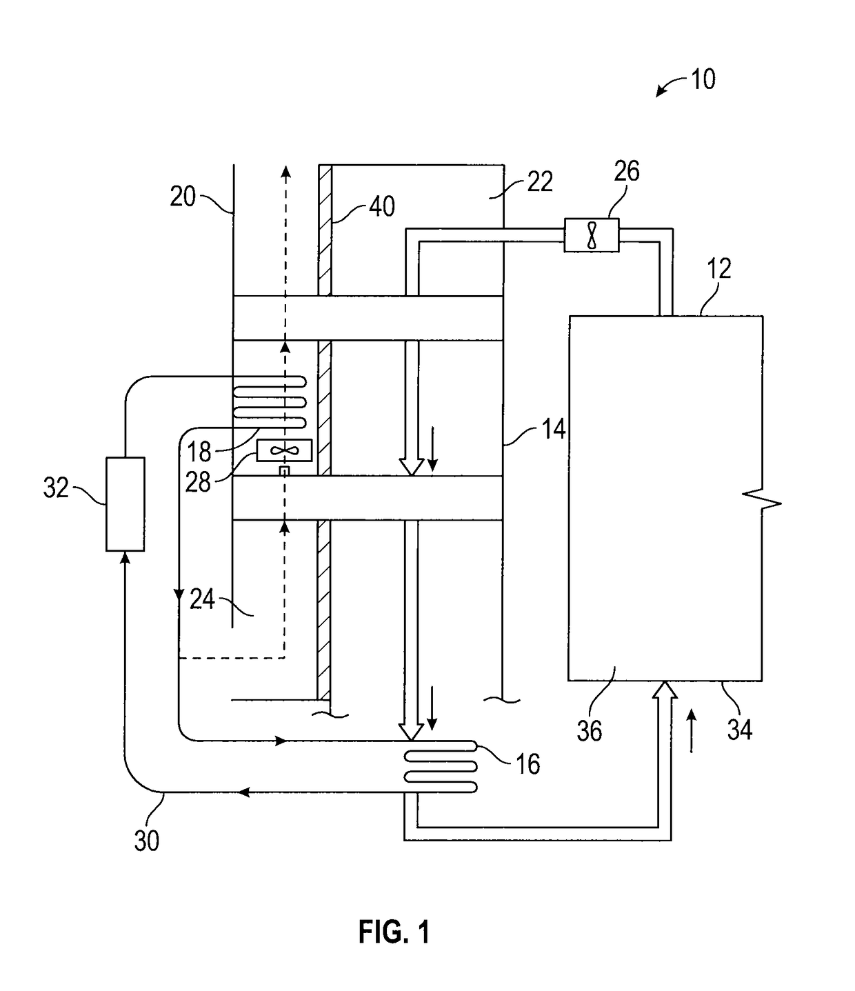
[0066]In some applications, the humidity level in the closed agricultural system requires more extensive dehumidification than normal. As shown in FIG. 6, a second desiccant wheel is installed downstream of the recirculation fans and condensing coil. The enthalpy wheel is replaced with a heat wheel (sensible heat-only wheel, no desiccant). A condensing coil or a natural gas burner acts as regeneration heat for the latent heat-only wheel. As the desiccant wheel rotates from one air stream to the other it adsorbs the moisture from the recirculation air. That moisture is then released to the outside air stream. To aid in that release, regeneration heat (condensing coil heat and / or optional natural gas burner) is applied to the air entering the wheel in the outside air stream. An additional set of temperature and relative humidity sensors are installed downstream of the desiccant wheel. The control system varies the speed of the desiccant wheel to meet the user defined relative...

Example

EXAMPLE 2

[0067]The efficiency of the air handling system depends on the outside air temperature and humidity. When conditions are favorable (cooler dryer weather), the system is capable of transferring the heat and humidity of the recirculation air through the enthalpy wheel to the cooler and dryer outside air. As indicated in the flow diagram shown in FIG. 7, 57° F. outside air with 40.7 grains of moisture is coming into the unit and into the enthalpy wheel. The resulting recirculation air temperature and grain level off the wheel (60° F. / 45.1 grains) to provide 100% of the required heating and dehumidification.

Example

EXAMPLE 3

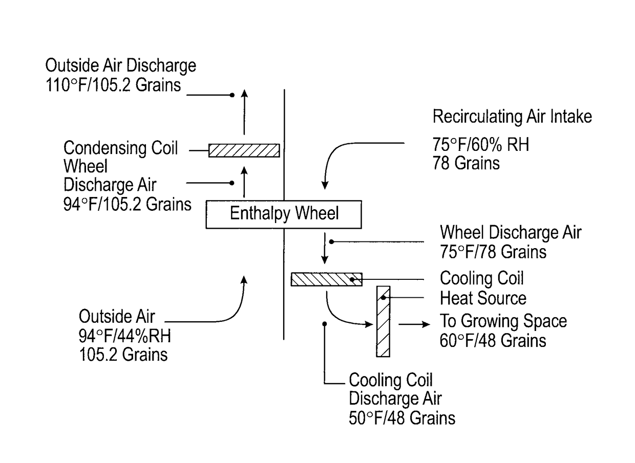
[0068]As the outside air temperature and humidity go up, the enthalpy wheel can still provide value by “pre-conditioning” the recirculation air before the cooling coil. In the flow diagram shown in FIG. 8, 57° F. outside air with 60.6 grains is entering the air handling unit and the enthalpy wheel. The resulting recirculation air temperature and grain level off the wheel (60° F. / 63.2 Grains) is sufficient to cool the recirculating air, but it is not sufficient to remove the moisture from the recirculating air. As a result the air handling unit control system shall enable the mechanical cooling to remove the additional grains of moisture from the recirculation air, down to the user defined set point of 48 grains. In order to remove the moisture the cooling coil must over cool the air, 50° F. The over cooled air could potentially over cool the recirculating air, therefore the air handling unit control system shall enable the heat source to heat the recirculating air to the us...


PUM


Abstract

A controlled and closed agricultural system includes a growing space and an air handling system having an enthalpy wheel and cooling coil. The enthalpy wheel is capable of transferring sensible and latent heat and is positioned in and rotatable through a recirculating air duct and an outside air duct. The recirculating air duct is in fluid connection with the growing space and one or more recirculation fans, while the outside air duct is in fluid connection with one or more outside air fans positioned to cause outside air to flow countercurrent to recirculating air. A cooling coil is positioned within the recirculating air duct, downstream of and in series with the enthalpy wheel. The cooling coil circulates a heat transfer fluid to remove additional heat from the recirculating air.

Description

BACKGROUND OF THE PRESENTLY DISCLOSED INVENTIVE CONCEPTS[0001]1. Field of the Presently Disclosed and / or Claimed Inventive Concepts[0002]The inventive concepts disclosed and claimed herein relate generally to systems and methods for controlling the interior environment of an enclosure, and more particularly, but not by way of limitation, to systems and methods for controlling the temperature, humidity, and optionally CO2 levels in a contained space.[0003]2. Brief Description of Related Art[0004]Greenhouses require temperature and humidity control to maintain dry foliage and plant health. Lighting can cause excessive heat and high humidity, especially free water on the plant foliage, promotes the development of foliar diseases, such as tomato blight, gray mold, and mildews in various crops. Such diseases substantially reduce crop yield, impair product quality, and require pesticides for control.[0005]Replacing the greenhouse air with external air is a customary method for decreasing ...

Claims


Application Information

Patent Timeline
IPC IPC(8): A01G9/18A01G7/04A01G9/24A01G7/02A01G9/20A01G1/00
CPCA01G9/18A01G9/20A01G7/045A01G9/246A01G7/02A01G1/001F24F3/1423F24F3/147Y02A40/25A01G9/249
Inventor ZIMMERMAN, JOHNWHALEY, CHRISTOPHER
Owner HARVEST AIR LLC
Why Eureka
Try Eureka