
On-board solar battery module

a solar battery and module technology, applied in the field of on-board solar battery modules, can solve the problems of increasing the number of parts, increasing the complexity of the structure, and the concern of a drop in the flexural rigidity of the on-board solar battery module at this section, and achieve the effect of controlling the buckling

Active Publication Date: 2017-04-13
TOYOTA JIDOSHA KK +1
View PDF7 Cites 6 Cited by
  • Summary
  • Abstract
  • Description
  • Claims
  • Application Information

AI Technical Summary

Benefits of technology

The present invention provides an on-board solar battery module with a simple structure that reduces weight and ensures flexural rigidity at the section that attaches to a vehicle body. The module has a top surface layer made of a resin panel, which reduces weight but increases the coefficient of linear expansion compared to inorganic glass. However, the back surface layer also has a resin panel, which helps control buckling and ensures flexural rigidity. The module is secured to the vehicle body at the section that does not have the encapsulant layer and back surface layer stacked thereunder, ensuring flexural rigidity and controlling buckling. The panel thickness of the peripheral edge portion of the top surface layer is thicker than the general portion to ensure flexural rigidity and control buckling. The raised portion on the back surface layer helps control flexural deformation of the module. Overall, the invention provides a lightweight and flexible solar battery module for vehicles.

Problems solved by technology

The type of solar battery module that attaches to the roof of a vehicle as described above requires the support member for attachment to the roof of the vehicle, so the number of parts increases and the structure becomes complicated.
That is, because at least part of the peripheral edge portion of the top surface layer does not have the encapsulant layer and the back surface layer stacked thereunder, there is the concern that there will be a drop in the flexural rigidity of the on-board solar battery module at this section.

Method used


Image

  • On-board solar battery module
  • On-board solar battery module
  • On-board solar battery module

Examples


Embodiment Construction

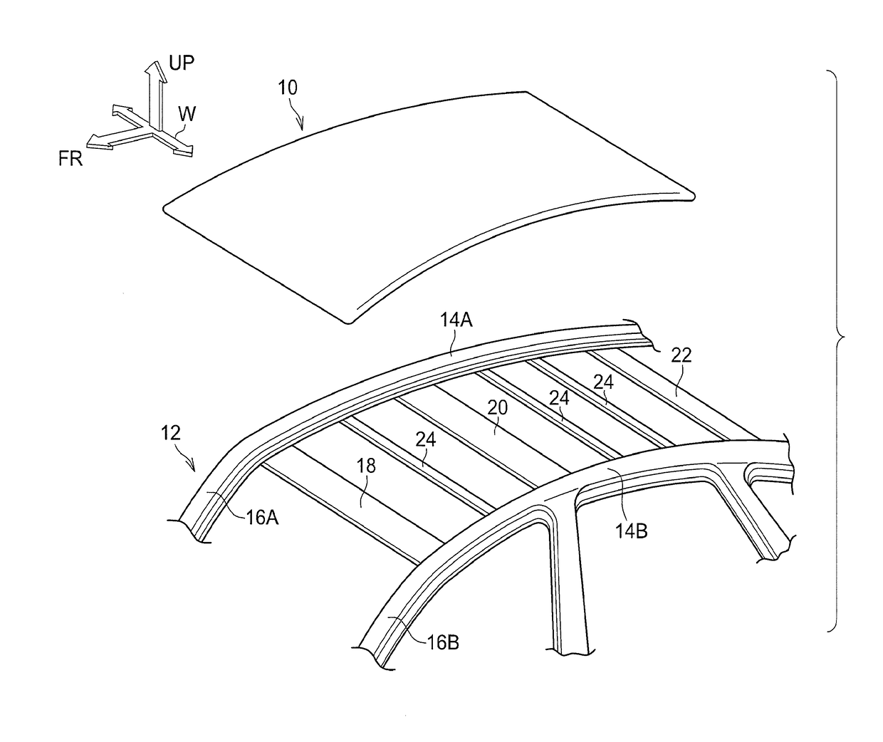
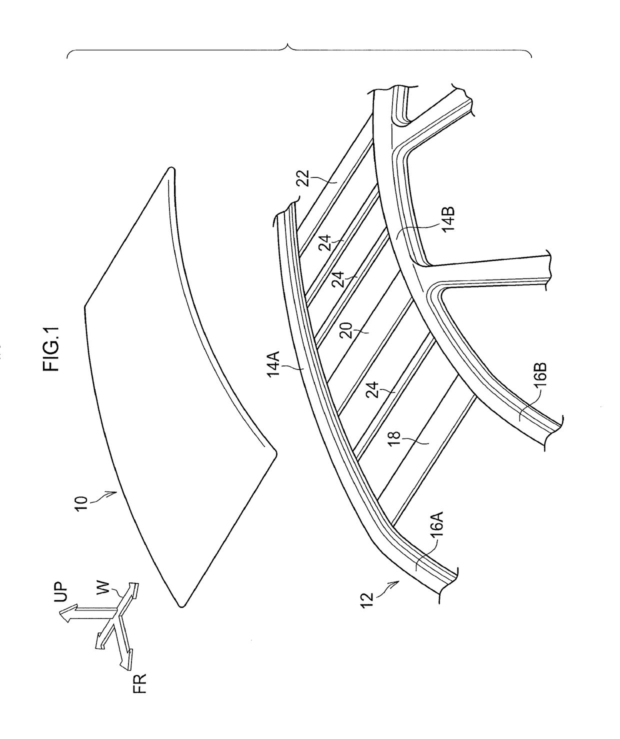
[0026]An on-board solar battery module 10 pertaining to an embodiment of the present invention will now be described with reference to FIG. 1 to FIG. 6. It should be noted that the on-board solar battery module 10 pertaining to the present embodiment is attached as a roof of a vehicle body to vehicle skeleton members. Furthermore, the drawings are representative, and parts having little association with the present invention are not shown in the drawings. Moreover, in FIG. 1, arrow FR indicates a vehicle forward direction, arrow W indicates a vehicle width direction, and arrow UP indicates a vehicle upward direction.

[0027](Configuration)

[0028]As shown in FIG. 1 the on-board solar battery module 10 for an automobile pertaining to the present embodiment is attached as a roof to a vehicle body 12. The vehicle body 12 has, as members that support the on-board solar battery module 10, a pair of roof side rails 14A and 14B that are disposed on both vehicle width direction end portions and...


PUM


Abstract

An on-board solar battery module includes: an encapsulant layer of power generating elements; a top surface layer joined to the encapsulant layer on the side corresponding to a light receiving surface side of the power generating elements; and a back surface layer joined to the encapsulant layer on the side opposite the side corresponding to the light receiving surface side of the power generating elements. Furthermore, an end portion of the back surface layer is positioned on the inner side of an end portion of the top surface layer in an extension direction of the top surface layer, and the top surface layer has a general portion that covers the power generating elements, and a peripheral edge portion that is formed at an end portion side thereof on the outer side of the general portion, and that has a thicker panel thickness than that of the general portion.

Description

CROSS-REFERENCE TO RELATED APPLICATION[0001]This application claims priority under 35 USC 119 from Japanese Patent Application No. 2015-199553 filed on Oct. 7, 2015, the disclosure of which is incorporated by reference herein.BACKGROUND[0002]Technical Field[0003]The present invention relates to an on-board solar battery module.[0004]Related Art[0005]Conventionally, a type of solar battery module has been proposed where a backsheet, an encapsulant film in which solar battery cells are encapsulated, and a top film are stacked on top of each other, with the encapsulant film being sandwiched between the backsheet and the top film. This type of solar battery module is configured in such a way that, as described in Japanese Patent Application Laid-open (JP-A) No. 2012-33573, the reverse surface of the backsheet is supported by a frame-shaped support member and is secured via the support member to the roof of a vehicle.[0006]Another type of solar battery module is being developed which, in...

Claims


Application Information

Patent Timeline
Patent Type & Authority Applications(United States)
IPC IPC(8): H02S10/40H02S30/10H01L31/048
CPCH02S10/40B62D25/06H02S30/10H01L31/048Y02E10/50
Inventor SAKABE, MOTOYAOGATA, KAZUYOSHIINABA, HIROTAKA
Owner TOYOTA JIDOSHA KK
Learn More