Method and device for operating a pressure reservoir, in particular for common rail injection systems in automobile engineering

a pressure reservoir and pressure technology, which is applied in the direction of fuel injecting pumps, machines/engines, electrical control, etc., can solve the problems of fuel supply branch not being able to meet the requirements of fuel supply, system overpressure or underpressure, etc., and achieve high operational reliability and keep the target rang

Active Publication Date: 2017-04-20
VITESCO TECH GERMANY GMBH
View PDF4 Cites 11 Cited by
  • Summary
  • Abstract
  • Description
  • Claims
  • Application Information

AI Technical Summary

Benefits of technology

[0008]In the context of pressure accumulator systems in general, against the background of the prior art, the present invention is based on the object of providing a method and a device for operating a pressure accumulator, which method and device combine high operational reliability with the least possible outlay in terms of construction and process, and make it possible for the pressure in the pressure accumulator to be kept in a target range as reliably as possible.

Problems solved by technology

If a high-pressure sensor of said type is defective, the regulation no longer functions, resulting in an overpressure or an underpressure in the system.
There is then a resulting risk in particular if no pressure-limiting valve is provided in the system.
Normally, such regulating systems are also combined with pressure dissipation valves which permit the dissipation of overpressure in the pressure accumulator, which is not possible in the supply branch of the fuel.

Method used


Image

  • Method and device for operating a pressure reservoir, in particular for common rail injection systems in automobile engineering
  • Method and device for operating a pressure reservoir, in particular for common rail injection systems in automobile engineering
  • Method and device for operating a pressure reservoir, in particular for common rail injection systems in automobile engineering

Examples


Embodiment Construction

[0034]The following description of the preferred embodiment(s) is merely exemplary in nature and is in no way intended to limit the invention, its application, or uses.

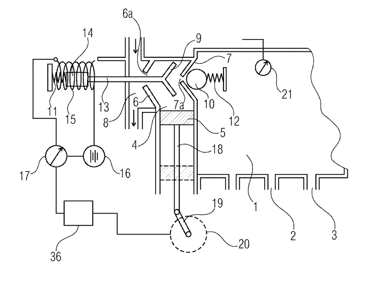
[0035]FIG. 1 schematically shows a pressure accumulator 1, which may be formed for example by a common-rail pressure accumulator in a fuel injection system of a vehicle. On the lower part of the pressure accumulator 1 there are illustrated outlets 2, 3, where injection valves are commonly arranged. For the sake of clarity, these have been omitted in the present drawing.

[0036]The device according to the invention is provided for providing fluid, in the present case that is to say a liquid in the form of fuel, in the pressure accumulator, or delivering said liquid into the pressure accumulator, at high pressure, typically several hundred bar. For this purpose, a pump chamber 4 is provided which is delimited in the fluid inlet region by a first wall 6, in the fluid outlet region by a second wall 7, and additionally by a ...


PUM


Abstract

A method and to a device for operating a pressure reservoir, where during a compression phase in a pump chamber, a pump periodically increases the pressure of a fluid located therein, and by means of a discharge valve controlled by differential pressure fluid under high pressure is allowed to be introduced from the pump chamber into the pressure reservoir. During a decompression phase following a compression phase, fluid from a fluid reservoir is introduced into the pump chamber by means of a controllable intake valve. In order to be able also to operate the pressure reservoir without a high pressure measurement directly in the pressure reservoir, the fluid pressure in the pressure reservoir is ascertained by means of a pressure determination in the pump chamber. The pressure determination takes place indirectly, monitoring of the intake valve in the decompression phase.

Description

CROSS-REFERENCE TO RELATED APPLICATIONS[0001]This application is a national phase application of PCT / EP2015 / 054658, filed Mar. 3, 2015, which claims priority to German Application No. 10 2014 206 442.2 filed Apr. 3, 2014. The disclosures of the above applications are incorporated herein by reference.FIELD OF THE INVENTION[0002]The invention relates generally to a method and device for operating a pressure reservoir, in particular for common rail injection systems in automobile engineering. The invention lies in the field of electrical engineering and mechanical engineering, and is concerned with devices and methods for operating a pressure accumulator, in particular for common-rail systems in automotive engineering. More specifically, the invention is concerned with the need for maintaining a controllable fluid pressure in a pressure accumulator of said type, in particular also when fluid intentionally or unintentionally escapes from the pressure accumulator and new fluid must be in...

Claims


Application Information

Patent Timeline
Patent Type & Authority Applications(United States)
IPC IPC(8): F02D41/38F02M59/44F02M37/04
CPCF02D41/3845F02M59/44F02M37/04
Inventor ANETSBERGER, DANIELCHIA, TET KONG BRIANSASSLER, WALTER
Owner VITESCO TECH GERMANY GMBH
Why Eureka
Try Eureka