Rolling bearing unit with rotational speed detecting device

a technology of rotating speed detection and rolling bearing, which is applied in the direction of bearing unit rigid support, instruments, transportation and packaging, etc., can solve the problems of difficult to completely extinguish the gap, and achieve the effect of convenient machined, improved detection accuracy, and sufficient sealing performance of the cap

Inactive Publication Date: 2017-04-20
NSK LTD
View PDF11 Cites 0 Cited by
  • Summary
  • Abstract
  • Description
  • Claims
  • Application Information

AI Technical Summary

Benefits of technology

[0039]According to the present invention configured as described above, sealing performance by the cap can be sufficiently secured.
[0040]That is, in the present invention, in the state where the cap is mounted on the axially inboard end of the outer ring by the insert cylindrical part of the fitting insert, the cap closes the axially outboard end opening of the through-hole formed in the cap bottom part. Therefore, even when a foreign material such as water is invaded into an axially outboard end of the portion between the outer circumferential surface of the sensor holder and the inner circumferential surface of the through-hole, this foreign material can be prohibited from being invaded into the space in which the rolling elements or the encoder is installed by the axially inboard surface of the insert bottom part. That is, the formation of the gap connected to the space in which the encoder is installed between the through-hole provided in the cap body and the sensor insertion ring fitted into this through-hole, which becomes the problem in the above-described conventional structure, can be avoided. Therefore, according to the present invention, sealing performance by the cap can be sufficiently secured.
[0041]The axial thickness dimension of the portion of the insert bottom part of the fitting insert, which axially faces the through-hole, is smaller than the thickness dimension of the remaining portion of the insert bottom part other than the portion. Therefore, even when a thickness dimension of the metal plate forming this fitting insert is increased to secure rigidity of the fitting insert, detection accuracy of the sensor is improved by reducing the axial distance between the sensor held in the sensor holder and the encoder.
[0042]The seal member is provided at the portion between the inner circumferential surface of the through-hole of the cap body and the outer circumferential surface of the sensor holder. Therefore, a foreign material such as water is effectively prevented from being invaded into the relevant portion. As a result, the water invaded into the relevant portion is prevented from being frozen and expanded to damage the sensor, or a gap is prevented from occurring at a coupled part between the fitting insert and the cap body.
[0043]The mounting nut has the tabular shape, both ends of which are axially open. Therefore, in comparison with a mounting nut having a structure in which one axial end thereof is closed, an internal thread part can be easily machined by, for instance, rolling, and a manufacturing cost is reduced. In a state where the mounting nut is molded in the cap bottom part, the axially outboard end opening of the mounting nut is closed by the fitting bottom part. Therefore, even when a foreign material such as water is invaded into the axially outboard end of the portion between the inner circumferential surface (the internal thread part) of the mounting nut and the outer circumferential surface (the external thread part) of the bolt, this foreign material can be prohibited from being invaded into the space in which the rolling elements or the encoder is install by the axially inboard surface of the insert bottom part. Accordingly, the sealing performance by the cap can be sufficiently secured.
[0044]The anti-rotation mechanism or the retaining mechanism is provided between the fitting insert and the cap body. Therefore, a coupling and fixing force between the fitting insert and the cap body can be made strong.

Problems solved by technology

However, in the conventional structure as described above, there is a possibility of causing the following problems.
For this reason, it is difficult to completely extinguish the gap.

Method used


Image

  • Rolling bearing unit with rotational speed detecting device
  • Rolling bearing unit with rotational speed detecting device
  • Rolling bearing unit with rotational speed detecting device

Examples


first example of embodiment

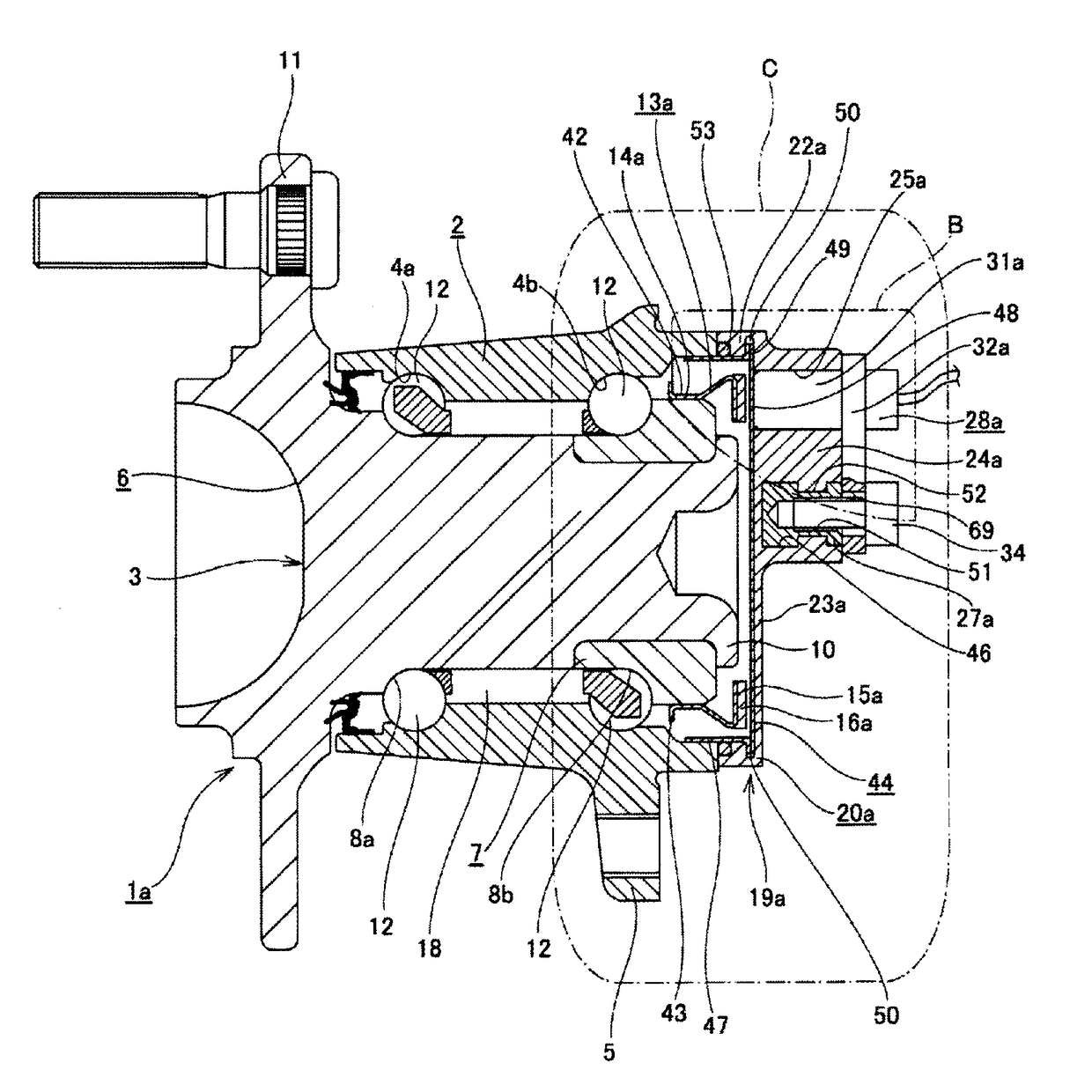
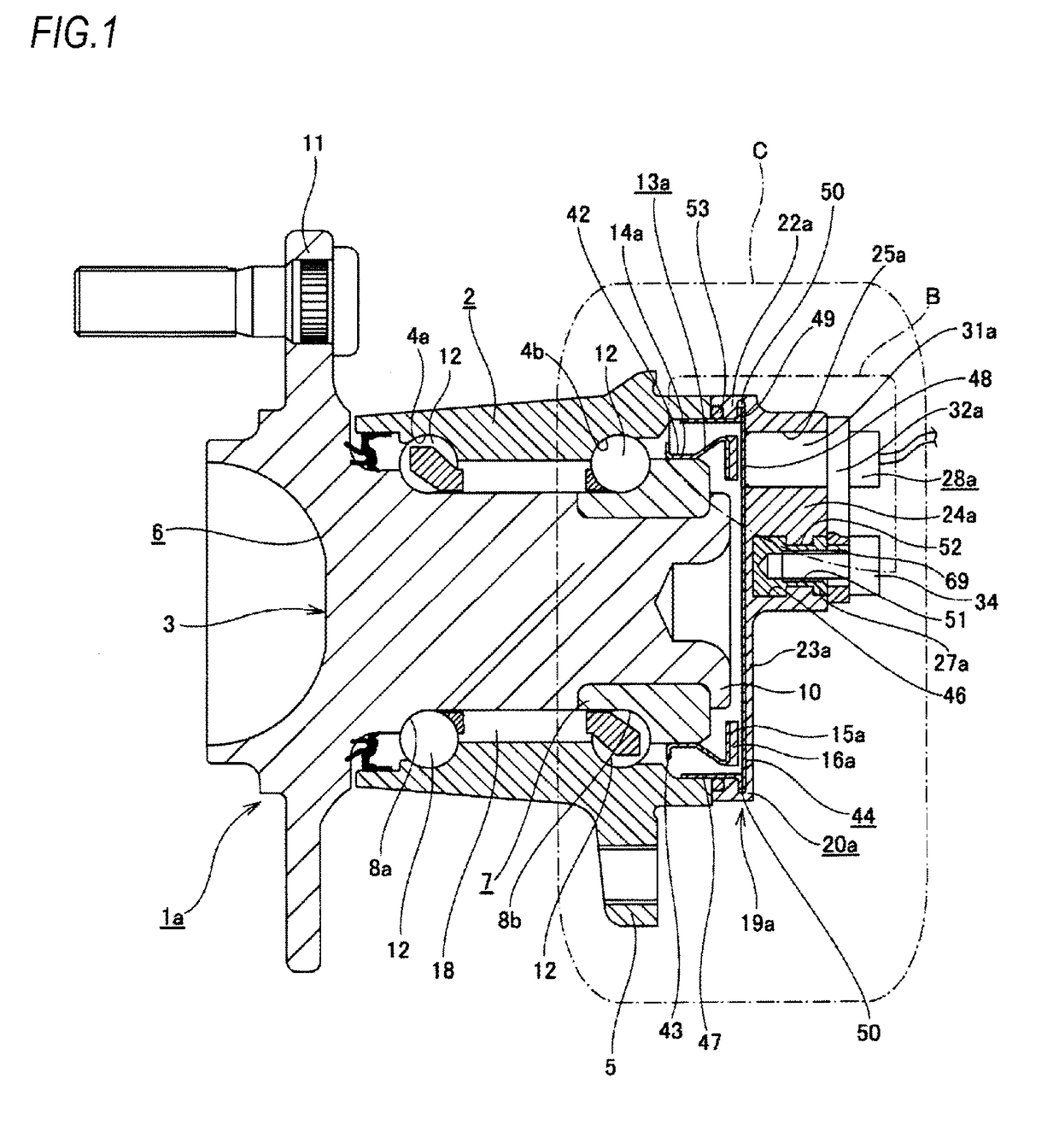
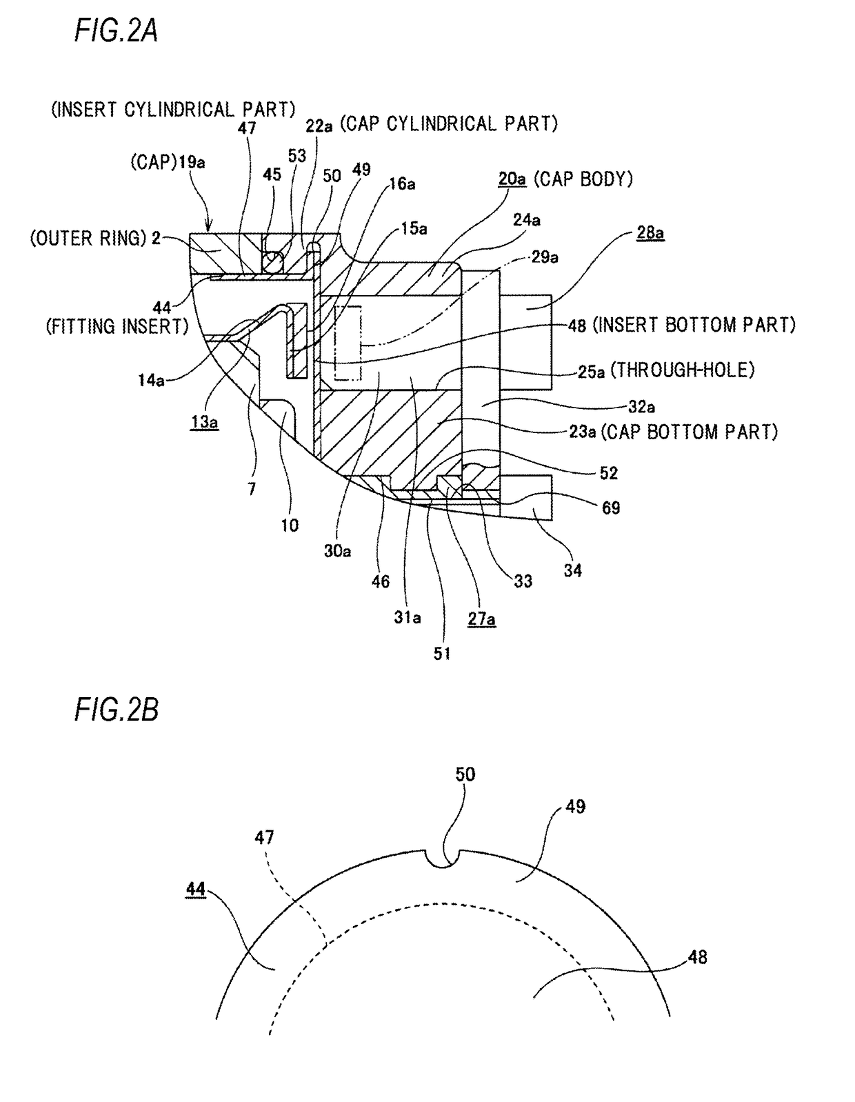
[0064]FIGS. 1 to 3 show a first example of an embodiment of the present invention. A feature of this example is that a structure of a cap 19a for closing an axially inboard end opening of an outer ring 2 is devised. Since structures and operational effects of other portions are basically the same as in the above-described conventional structure, overlapping illustration and description will be omitted or simplified. The following description is based on characteristic portions of this example and the portions which are not described previously.

[0065]A rolling bearing unit la with a rotational speed detecting device of this example rotatably supports a wheel which is a non-driven wheel on a suspension such as a knuckle, detects a rotational speed of this wheel, and rotatably supports a hub 3 which is a rotatable ring at an inner diameter side of the outer ring 2 which is a stationary ring via a plurality of rolling elements 12, 12.

[0066]The outer ring 2 and a hub body 6 constituting ...

second example of embodiment

[0099]FIGS. 4 to 7 show a second example of the embodiment of the present invention.

[0100]In a rolling bearing unit with a rotational speed detecting device of this example, insert through-holes 54, 54 passing through an insert bottom part 48a constituting a fitting insert 44a are formed at a plurality of circumferential places at a radially inner side of a middle part of the insert bottom part 48a with respect to a position facing a through-hole 25a of a mount part 24b in an assembled state.

[0101]In a state where the fitting insert 44a as described above is molded in a cap body 20b by injection molding, cap engagement parts 55, 55, each of which has a greater diameter dimension of an circumscribed circle than each of the insert through-holes 54, 54, are provided for portions around the insert through-holes 54, 54 at the axially outboard side with respect to an axially outboard surface of the insert bottom part 48a. Each of the cap engagement parts 55, 55 and the cap bottom part 23b...

third example of embodiment

[0111]FIG. 8 shows a third example of the embodiment of the present invention.

[0112]In a rolling bearing unit with a rotational speed detecting device of this example, a sensor seating surface 65 is formed at a portion, which faces a through-hole 25a of a cap bottom part 23b constituting a cap body 20c, of an axially inboard surface of an insert bottom part 48c of a fitting insert 44b, and has an axial thickness dimension L1 smaller than an axial thickness dimension L2 of the other portion (L12). In this example, this sensor seating surface 65 is formed, for example, by coining a portion, which faces the through-hole 25a, of a fitting insert 44 (see FIG. 1) whose axially inboard surface is flat like the above-described first example of the embodiment, and moving a part of a metal, which is present in the portion, to a periphery of the relevant portion. In this example, with the formation of the sensor seating surface 65 according to the coining process as described above, an annular...


PUM


Abstract

There is provided a structure capable of sufficiently securing sealing performance by a cap (19a). In a state where a fitting insert (44) formed of a nonmagnetic material having a bottomed cylindrical shape is fixed to an inner diameter side of a cap cylindrical part (22a) constituting a cap body (20a) formed of a synthetic resin having a bottomed cylindrical shape, an axially outboard end opening of a through-hole (25a) formed in a cap bottom part (23a) of the cap body (20a) is closed by an axially inboard surface of an insert bottom part (48) of the fitting insert (44). An outer circumferential surface of an insert cylindrical part (47) of the fitting insert (44) is directly fitted into and fixed to an inner circumferential surface of an axially inboard end of an outer ring (2).

Description

TECHNICAL FIELD[0001]The present invention relates to an improvement to a rolling bearing unit with a rotational speed detecting device, which is used for rotatably supporting a wheel (a non-driven wheel) of a vehicle on a suspension and for detecting a rotational speed of this wheel.BACKGROUND ART[0002]A rolling bearing unit is used to rotatably support a wheel of a vehicle on a suspension. To control an Anti-lock Braking System (ABS) or a Traction Control System (TCS), there is a need to detect a rotational speed of the wheel. For this reason, rotatably supporting the wheel on the suspension and detecting the rotational speed of this wheel using a rolling bearing unit with a rotational speed detecting device in which the rotational speed detecting device is incorporated into the rolling bearing unit have recently been widely adopted.[0003]As an example of a conventional structure of the rolling bearing unit with the rotational speed detecting device used for this purpose, a struct...

Claims


Application Information

Patent Timeline
Patent Type & Authority Applications(United States)
IPC IPC(8): F16C41/00B60B27/00F16C33/78G01P3/44F16C19/18F16C33/72
CPCF16C41/007F16C19/186F16C33/723F16C33/783G01P3/443B60B27/065B60B27/0005B60B27/0073B60B27/0094F16C2326/02F16C2233/00B60B27/0068F16C35/00
Inventor NAKAMURA, YUJI
Owner NSK LTD
Why Eureka
Try Eureka