Check patentability & draft patents in minutes with Patsnap Eureka AI!

Decoder and method for decoding an audio signal, encoder and method for encoding an audio signal

Active Publication Date: 2017-04-20
FRAUNHOFER GESELLSCHAFT ZUR FOERDERUNG DER ANGEWANDTEN FORSCHUNG EV
View PDF0 Cites 7 Cited by
  • Summary
  • Abstract
  • Description
  • Claims
  • Application Information

AI Technical Summary

Benefits of technology

The patent describes a method for improving the phase of an audio signal by using a processor or decoder that calculates the phase measure of the audio signal for a time frame and a target phase measure for the same time frame. The processor then corrects the phase of the audio signal for the time frame by using the calculated phase measure and the target phase measure. This results in a processed audio signal with improved phase accuracy. The method can be used in both the decoder and encoder, and can be implemented using different algorithms for the phase correction. The technical effect of the patent is improved audio signal quality with reduced distortion and improved phase accuracy.

Problems solved by technology

This step implies a loss of information and introduces a coding distortion (error, noise) into the signal.
Thus, at very low bit rates, not enough bits may be available to represent all coefficients in the precision that may be used for achieving perceptually unimpaired reproduction.
Vocoders and hybrid systems usually suffer from an artifact called phasiness [8] which can be attributed to the loss of vertical phase coherence.
State-of-the-art audio coders [1] usually compromise the perceptual quality of audio signals by neglecting important phase properties of the signal to be coded.
However, not all kinds of phase coherence errors can be corrected at the same time and not all phase coherence errors are perceptually important.
Especially due to the application of audio bandwidth extension [2][3][4], the phase coherence over frequency and over time is often impaired.

Method used


Image

  • Decoder and method for decoding an audio signal, encoder and method for encoding an audio signal
  • Decoder and method for decoding an audio signal, encoder and method for encoding an audio signal
  • Decoder and method for decoding an audio signal, encoder and method for encoding an audio signal

Examples


Embodiment Construction

[0129]In the following, embodiments of the invention will be described in further detail. Elements shown in the respective figures having the same or a similar functionality will have associated therewith the same reference signs.

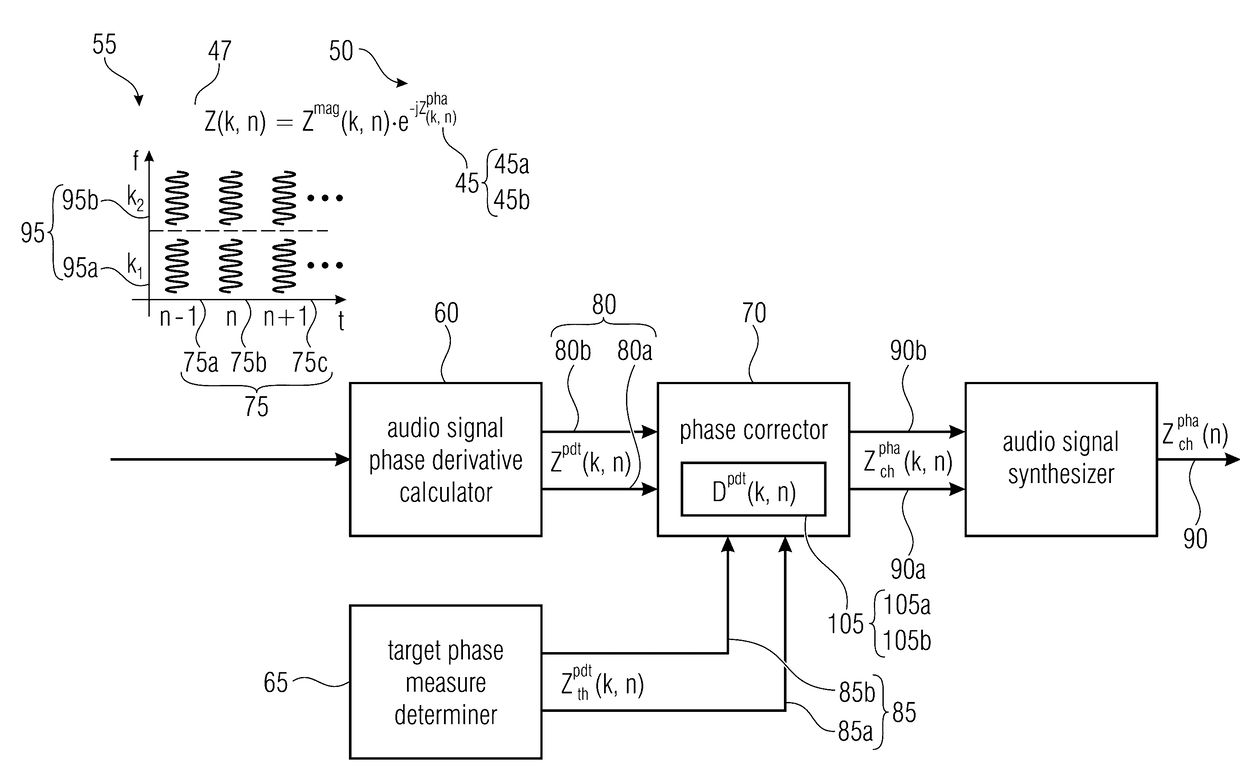
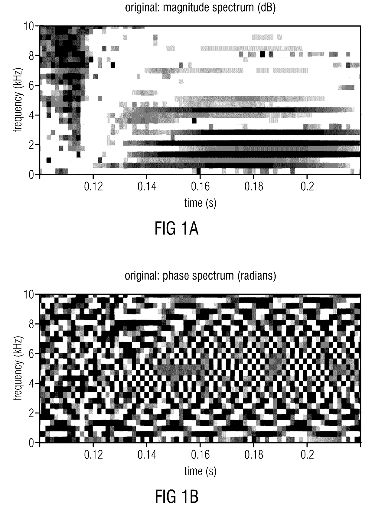
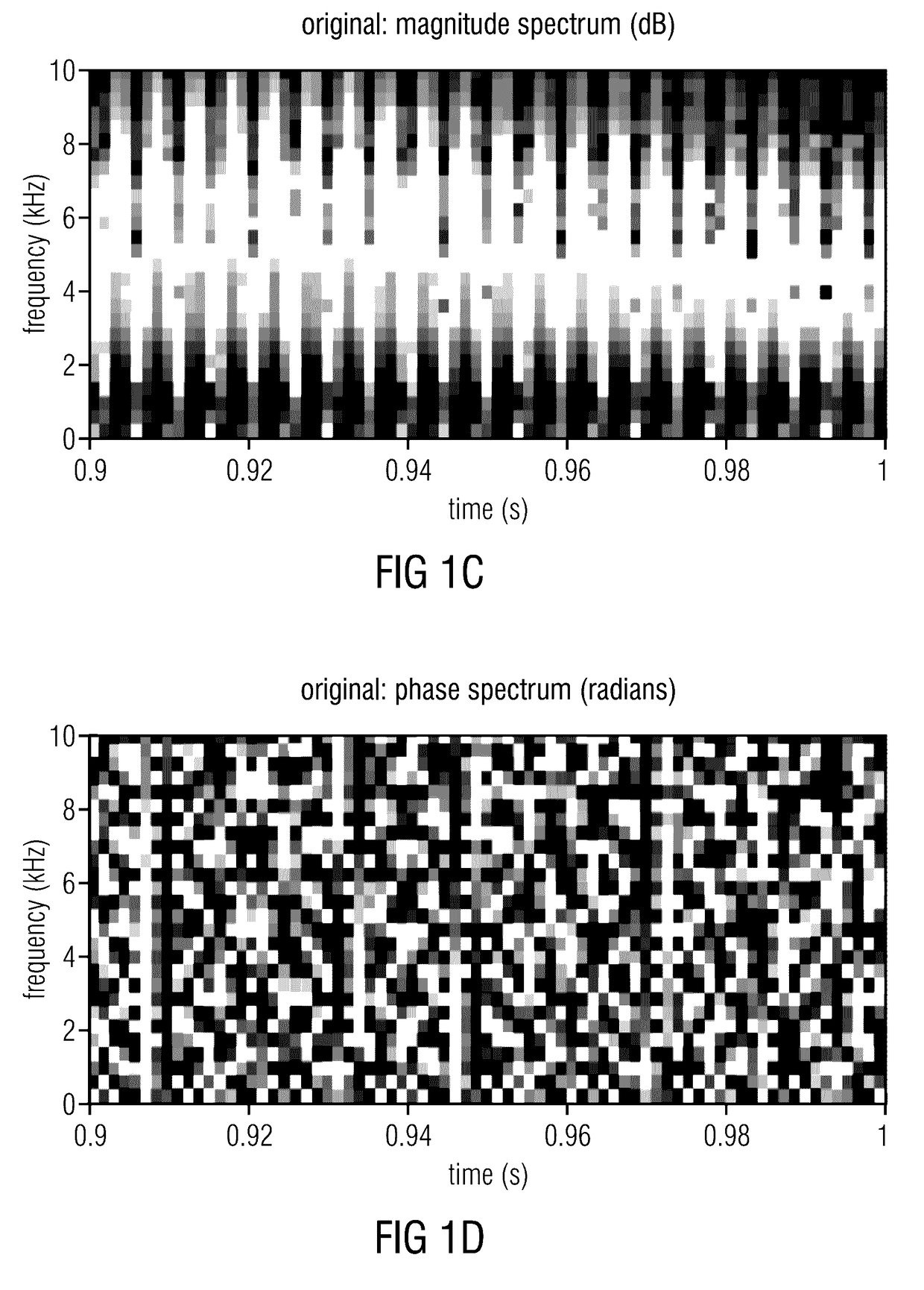
[0130]Embodiments of the present invention will be described with regard to a specific signal processing. Therefore, FIGS. 1-14 describe the signal processing applied to the audio signal. Even though the embodiments are described with respect to this special signal processing, the present invention is not limited to this processing and can be further applied to many other processing schemes as well. Furthermore, FIGS. 15-25 show embodiments of an audio processor which may be used for horizontal phase correction of the audio signal. FIGS. 26-38 show embodiments of an audio processor which may be used for vertical phase correction of the audio signal. Moreover, FIGS. 39-52 show embodiments of a calculator for determining phase correction data for an audio sig...


PUM


Abstract

A decoder for decoding an audio signal includes a first target spectrum generator for generating a target spectrum for a first time frame of a subband signal of the audio signal using first correction data. A first phase corrector for corrects a phase of the subband signal in the first time frame of the audio signal determined with a phase correction algorithm, the correction being performed by reducing a difference between a measure of the subband signal in the first time frame of the audio signal and the target spectrum. An audio subband signal calculator calculates the audio subband signal for the first time frame using a corrected phase for the time frame and for calculating audio subband signals for a second time frame different from the first time frame using the measure of the subband signal in the second time frame or using a corrected phase calculation in accordance with a further phase correction algorithm different from the phase correction algorithm.

Description

CROSS-REFERENCE TO RELATED APPLICATIONS[0001]This application is a continuation of copending International Application No. PCT / EP2015 / 064428, filed Jun. 25, 2015, which is incorporated herein by reference in its entirety, and additionally claims priority from European Applications Nos. EP 14 175 202.2, filed Jul. 1, 2014, and EP 15 151 463.5, filed Jan. 16, 2015, both of which are incorporated herein by reference in their entirety.[0002]The present invention relates to an audio processor and a method for processing an audio signal, a decoder and a method for decoding an audio signal, and an encoder and a method for encoding an audio signal. Furthermore, a calculator and a method for determining phase correction data, an audio signal, and a computer program for performing one of the previously mentioned methods are described. In other words, the present invention shows a phase derivative correction and bandwidth extension (BWE) for perceptual audio codecs or correcting the phase spec...

Claims


Application Information

Patent Timeline
IPC IPC(8): G10L19/02G10L19/18G10L19/025
CPCG10L19/0208G10L19/18G10L19/025G10L19/02G10L19/0204G10L21/007G10L21/038G10L19/00G10L21/02G10L19/22G10L21/01G10L19/26
Inventor DISCH, SASCHALAITINEN, MIKKO-VILLEPULKKI, VILLE
Owner FRAUNHOFER GESELLSCHAFT ZUR FOERDERUNG DER ANGEWANDTEN FORSCHUNG EV
Features
  • R&D
  • Intellectual Property
  • Life Sciences
  • Materials
  • Tech Scout
  • Unparalleled Data Quality
  • Higher Quality Content
  • 60% Fewer Hallucinations
Learn More