Circuit protection system and method

a protection system and circuit technology, applied in the direction of electrical equipment, electrical apparatus, etc., can solve the problems of utilizing communication cables, current electrical and building codes and standards do not address the issue of using communication cables, e.g., their conductors as power, significant damag

Active Publication Date: 2017-04-20
FOSTER FREDERICK M
View PDF6 Cites 48 Cited by
  • Summary
  • Abstract
  • Description
  • Claims
  • Application Information

AI Technical Summary

Problems solved by technology

Traditionally, communication circuits and associated wires and conductors were designed and intended for transmission of low power (i.e. phantom voltage) and data communication signals, and cabling systems and components were not originally designed to transmit high levels of power.
Unfortunately, current electrical and building codes and standards do not address the issue of utilizing communication cables (e.g., twisted pair based and / or coaxial cables) and their conductors as a power transmission medium.
However, as the trend toward PoE and similar technologies continue to evolve, without a circuit protection system, the equipment accessible to people can possibly result in significant damage.
With the current environment of rapid innovation within this vertical market, it will become increasingly difficult to regulate or enforce power based safety issues.
An example of this difficulty is to check a code compliant communication system that has been installed within a facility today.
However, it can still present many fire and safety problems if the next manager decides to install PoE++ or other powering technologies, which can be possibly up to 200 watts, since communication systems, including the cabling systems, were not originally designed to transmit such high power levels, and the cabling systems are located inside the walls and the detailed information about the cabling systems cannot be obtained easily.
As the power continues to increase within these cabling systems, ancillary ramifications will emerge.
The increase in heat can cause a vastly increased rise in temperature when these twisted pairs and coaxial cables are bundled such as in a riser, trunk, composite design, or when implemented in combined pathways.
The heat rise has the potential to melt current insulation and jacketing materials, and can possibly result in a condition of arcing and eventual fire.

Method used


Image

  • Circuit protection system and method
  • Circuit protection system and method
  • Circuit protection system and method

Examples


Embodiment Construction

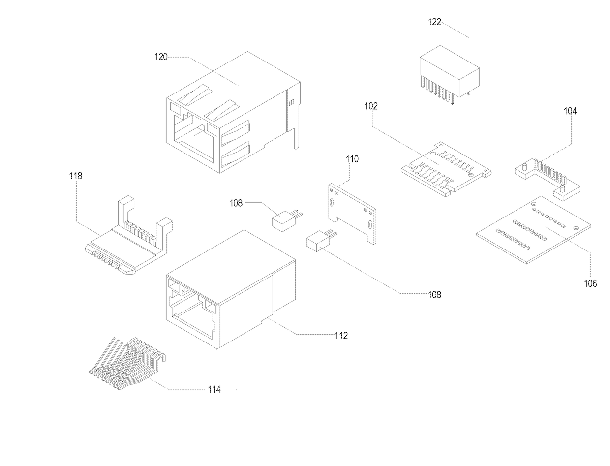
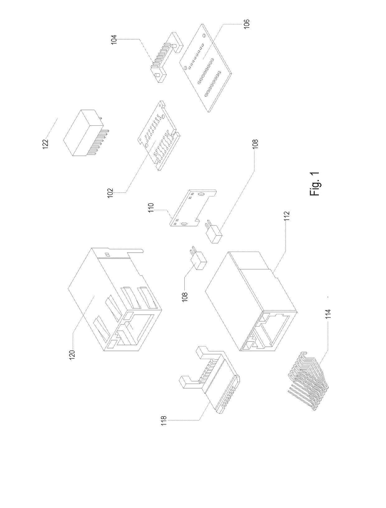
[0053]FIGS. 1 and 2 depict an exploded view of a circuit protection system according to the present disclosure.

[0054]In FIG. 1, a circuit protection system 100 comprises a PC board assembly 102, an Insulation Displacement Connector (IDC) assembly 104 that can terminate cable conductors, two status led indictors 108, a LED mounting board 110, an internal component housing 112, a Contact Tine Assembly 114 that provides the physical contact point for the associated mating plug, a Contact Tine Assembly holder 118, a housing 120 and a circuit protection module 122.

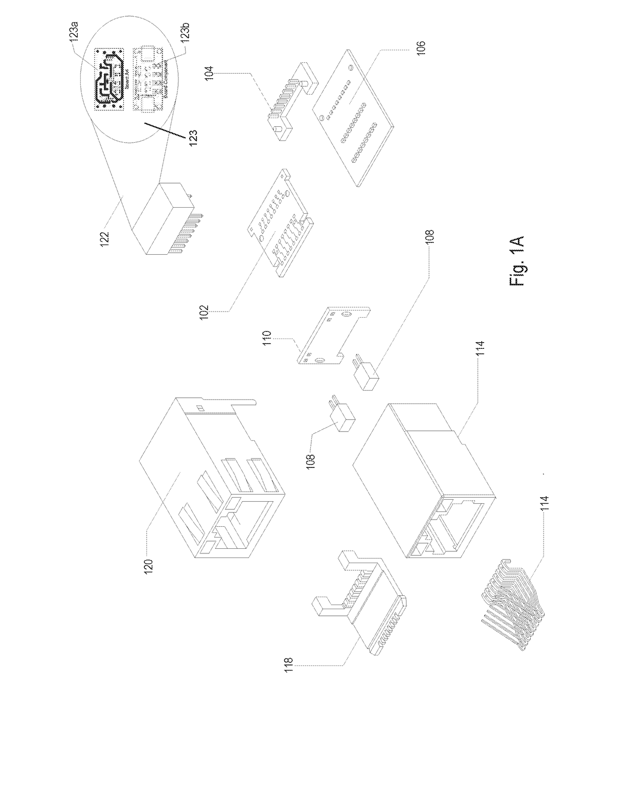
[0055]In FIG. 1A, the circuit protection module 122 includes a simple conductor interrupt control module (CICM) 123. Simple CICM 123 includes a board art diagram 123a and a board component diagram 123b. Board component diagram 123b for simple CICM 123 are described in FIGS. 3B, 3B-a and 3B-b.

[0056]In FIG. 1B, circuit protection module 122 includes a smart CICM 125. Smart CICM 125 includes a board art diagram 125a and a board co...


PUM


Abstract

A DC and / or an AC power transmission circuit protection system is for protection of a cabling medium. The circuit protection system includes a power supply, a powered device and a circuit protection module that includes an over-current and / or over-voltage circuit module and / or a heat circuit protector. The protection system is disposed between the power supply and the powered device, and interrupts an electrical current that flows through the cabling medium when the over-current and / or over-voltage circuit module and / or the circuit protector exceeds a predetermined level. There is also provided a method to dispose the circuit protection system and the circuit protection module within the circuit and to interrupt the circuit when over-current and / or over-voltage circuit module and / or heat circuit protector exceeds a predetermined level.

Description

CROSS-REFERENCE TO RELATED APPLICATIONS[0001]The present application claims the benefit of U.S. Provisional Application Ser. No. 62 / 242,534, filed Oct. 16, 2015, the entire contents of which are hereby expressly incorporated by way of reference.BACKGROUND OF THE DISCLOSURE[0002]1. Field of the Disclosure[0003]The present disclosure relates generally to a circuit protection system and a method for over-current and over-voltage protection for communication cabling medium and various traditional and emerging cable construction and materials of emerging devices. Emerging devices include, but are not limited to, currently known devices using Power over Ethernet (PoE) technology. More particularly, the present disclosure relates to a circuit protection system and a method to provide over-voltage and / or over-current protection for communication circuits and associated wires and conductors, especially, for the current National Electrical Code (NEC) classification Chapter 7 class 2 & 3 circu...

Claims


Application Information

Patent Timeline
Patent Type & Authority Applications(United States)
IPC IPC(8): H02H3/00H02H7/26H02H5/04
CPCH02H3/00H02H7/26H02H5/041H02H5/042H02H3/006H02H3/08H02H9/041H02H3/046H02H3/20
Inventor FOSTER, FREDERICK M.
Owner FOSTER FREDERICK M
Why Eureka
Try Eureka