Electro-acoustic conversion film and digital speaker

a technology of electroacoustic conversion and digital speakers, applied in the direction of electrical transducers, transducer types, electric/electrostrictive transducers, etc., can solve the problems of easy generation of pulse driving reverb, difficult high-bit realization, and increased noise, so as to reduce noise and improve sound quality , the effect of high sound quality

Inactive Publication Date: 2017-04-20
FUJIFILM CORP
View PDF5 Cites 5 Cited by
  • Summary
  • Abstract
  • Description
  • Claims
  • Application Information

AI Technical Summary

Benefits of technology

[0036]According to the electro-acoustic conversion film of the present invention, even when pulse driving is performed by a parallel PCM digital signal, reverberation hardly occurs and crosstalk between the divided electrodes (between segments) also hardly occurs. Therefore, a high sound quality digital spea

Problems solved by technology

Therefore, high-bit realization is difficult because of a unique resonance frequency and a narrow frequency band.
Further, in a digital speaker using a unimorph type piezoelectric element, reverberation is easily generated in pulse driving.
Further, in the digital speaker using a u

Method used


Image

  • Electro-acoustic conversion film and digital speaker
  • Electro-acoustic conversion film and digital speaker
  • Electro-acoustic conversion film and digital speaker

Examples


embodiment 1

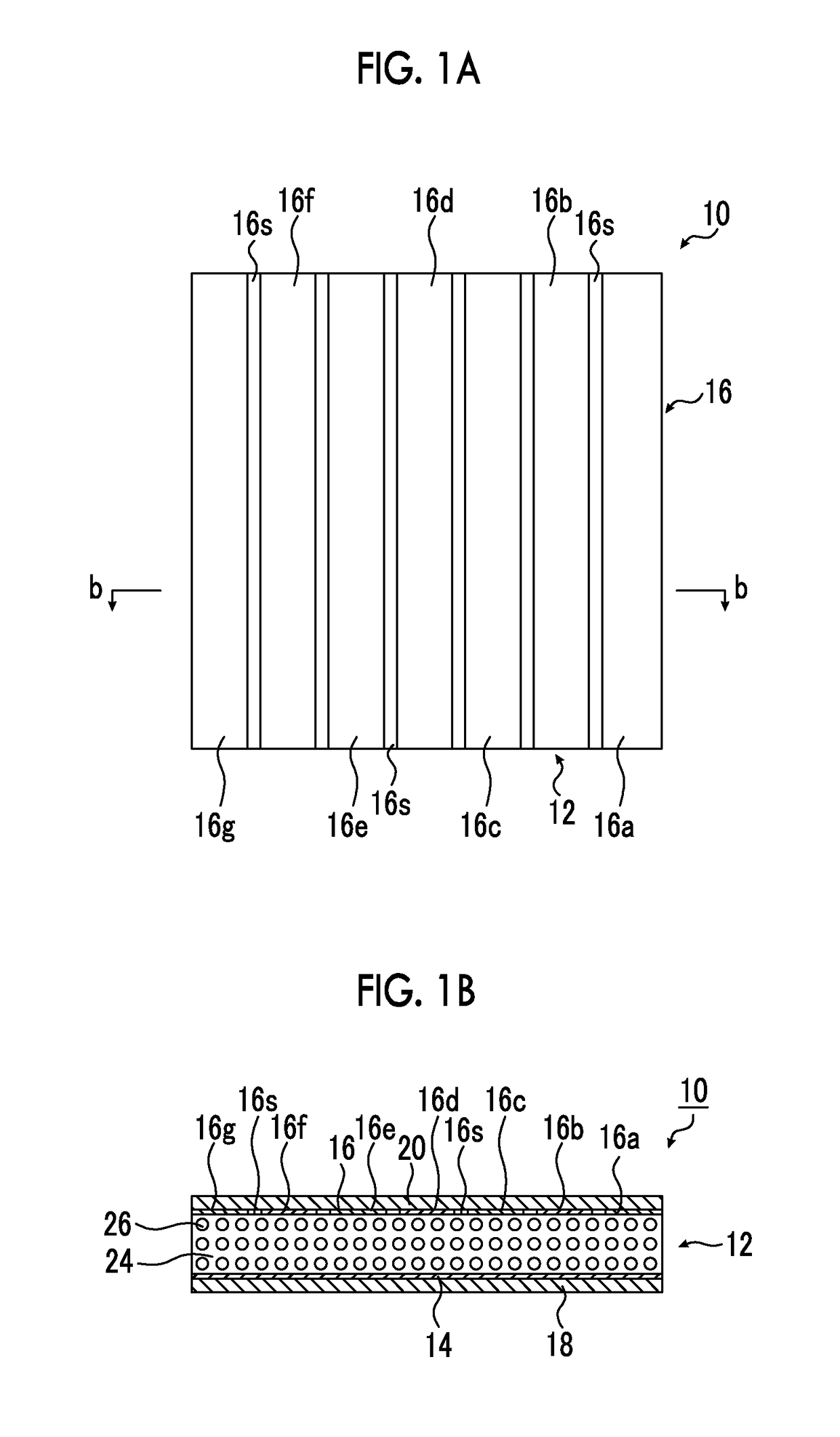
[0255]The conversion film 10 of the present invention illustrated in FIGS. 1A and 1B was prepared using the method illustrated in FIGS. 4A to 4E described above.

[0256]First, cyanoethylated PVA (CR-V manufactured by Shin-Etsu Chemical Co., Ltd.) was dissolved in dimethyl formamide (DMF) in a compositional ratio described below. Then, the PZT particles was added to this solution in the compositional ratio described below, dispersed by a propeller mixer (number of revolutions: 2000 rpm), and a coating material for forming the piezoelectric layer 12 was prepared.

PZT particles 300 parts by weightCyanoethylated PVA  30 parts by weightDMF  70 parts by weight

[0257]PZT particles obtained by sintering a commercially available PZT raw material powder at 1000° C. to 1200° C. and then crushing and classifying the powder so that an average particle size is 5 μm was used.

[0258]On the other hand, the sheet-like objects 10a and 10c obtained by vacuum-depositing a thin copper film having a thickness ...

embodiment 2

[0274]In the following compositional ratio, polyvinyl acetate (manufactured by Aldrich) was dissolved in dimethylformamide (DMF). Then, PZT particles were added to this solution in the following compositional ratio and dispersed with a propeller mixer (number of revolutions: 2000 rpm) to prepare a coating material for forming the piezoelectric layer 12.

PZT particles 200 parts by weight Poly vinyl acetate  20 parts by weightDMF  80 parts by weight

[0275]The PZT particles were produced, in the same manner as in Embodiment 1.

[0276]The conversion film 10 was produced in the same manner as in Embodiment 1 except that the piezoelectric layer 12 was formed using the coating material.

[0277]The same speaker as in Embodiment 1 was produced and evaluated in the same manner as in Embodiment 1. As a result, the evaluation was B.


PUM


Abstract

Provided is an electro-acoustic conversion film that is suitably used for a digital speaker or the like, and that includes a polymer composite piezoelectric body formed by dispersing piezoelectric particles in a viscoelastic matrix formed of a polymer material having viscoelasticity at room temperature, and thin-film electrodes provided on both surfaces of the polymer composite piezoelectric body, in which at least one of the thin-film electrodes is divided into a plurality of regions having the same area, and the respective regions are coupled in parallel and grouped to correspond to a weight of each bit digit of a parallel PCM digital signal. Thus, an electro-acoustic conversion film by which a digital speaker in which reverberation or crosstalk between segments is suppressed is obtained is provided.

Description

CROSS-REFERENCE TO RELATED APPLICATIONS[0001]This application is a Continuation of PCT International Application No. PCT / JP2015 / 068585 filed on Jul. 26, 2015, which claims priority under 35 U.S.C. §119(a) to Japanese Patent Application No. 2014-134468 filed on Jun. 30, 2014. The above application is hereby expressly incorporated by reference, in its entirety, into the present application.BACKGROUND OF THE INVENTION[0002]1. Field of the Invention[0003]The present invention relates to an electro-acoustic conversion film used in a digital acoustic device such as a digital speaker, and to a digital speaker using the same.[0004]2. Description of the Related Art[0005]A digital speaker is a speaker to which a digital signal (pulse) is directly input so as to obtain a conventional analog acoustic output. Here, an analog signal is sampled at regular intervals using a “sampling theorem”, and a pulse having a sample value is applied to the speaker and subjected to digital / analog conversion (D / ...

Claims


Application Information

Patent Timeline
IPC IPC(8): H04R17/00H01L41/047H01L41/257H01L41/29H01L41/193H04R1/00H01L41/09
CPCH04R17/005H04R1/005H01L41/047H01L41/257H01L41/29H01L41/193H01L41/09H10N30/852H10N30/045H10N30/06H10N30/20H10N30/87H10N30/857
Inventor MIYOSHI, TETSU
Owner FUJIFILM CORP
Why Eureka
Try Eureka