Torsional damping for gas turbine engines

a technology of torsional damping and gas turbine engine, which is applied in the direction of machines/engines, mechanical energy handling, mechanical apparatus, etc., can solve the problems of alternating mechanical torque reaching values, damage or fatigue of components of the rotor shaft system, and the torsional interaction between the power system components and the mechanical drive train, etc., to reduce the oscillating torque

Inactive Publication Date: 2017-04-27
GENERAL ELECTRIC CO
View PDF12 Cites 7 Cited by
  • Summary
  • Abstract
  • Description
  • Claims
  • Application Information

AI Technical Summary

Benefits of technology

[0011]In further embodiments, the controller may be configured to control a power factor of the generator so as to provide torsional damping of the generator by decreasing the power factor and creating losses internal to windings of the generator.
[0012]In additional embodiments, the torsional damper may be configured to reduce the oscillating torque between the generator and the turbine.

Problems solved by technology

The low mechanical damping in high power trains can cause torsional interaction between power system components and the mechanical drive train.
For example, if one of the natural frequencies of the mechanical drive train is excited to a torsional resonance, the resulting alternating mechanical torque can reach values that can damage or cause fatigue in components of the rotor shaft system.

Method used


Image

  • Torsional damping for gas turbine engines
  • Torsional damping for gas turbine engines
  • Torsional damping for gas turbine engines

Examples


Embodiment Construction

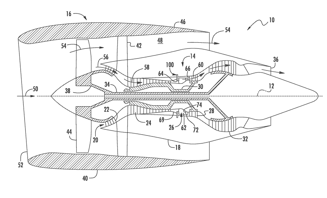
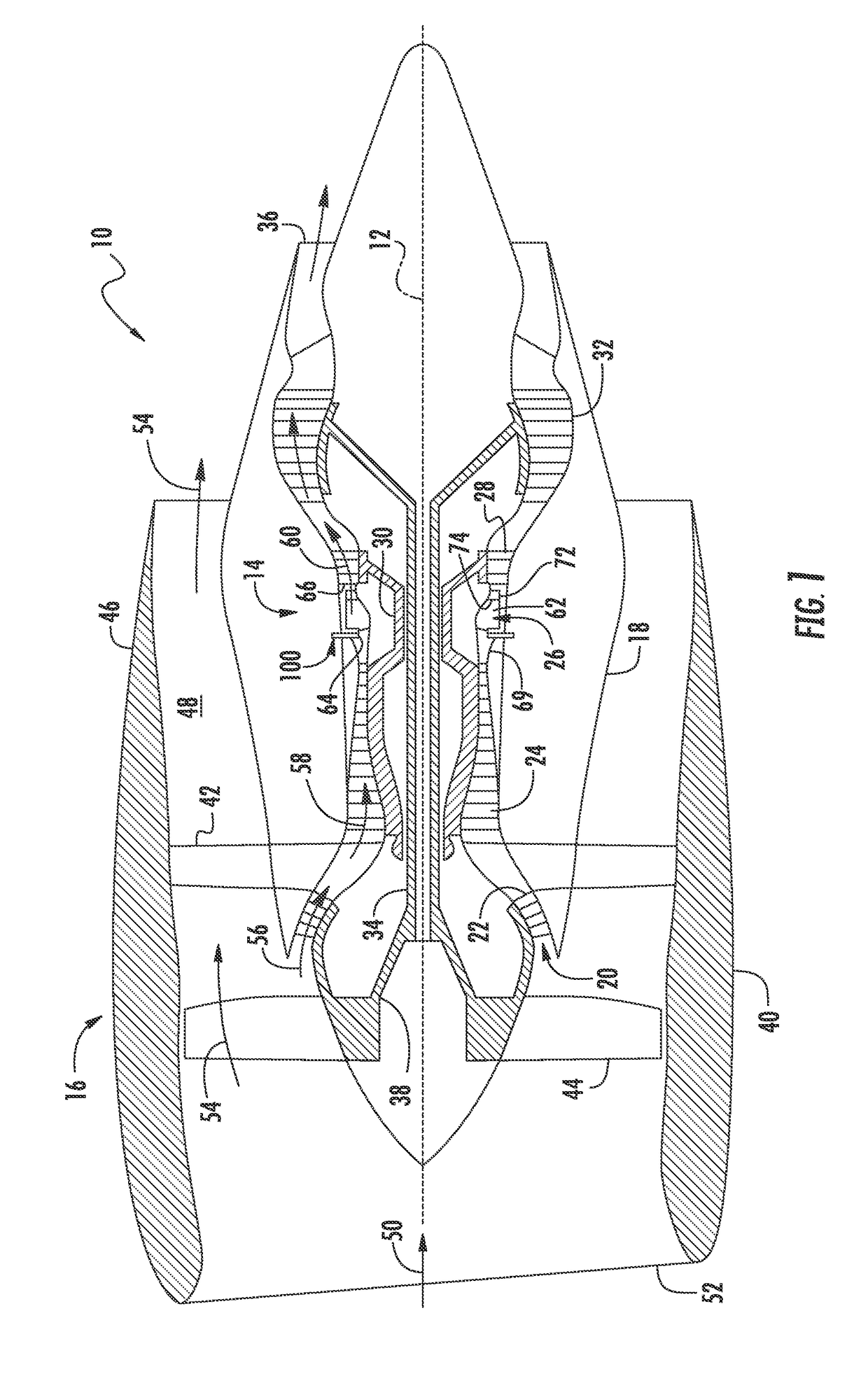
[0032]Reference will now be made in detail to present embodiments of the invention, one or more examples of which are illustrated in the accompanying drawings. The detailed description uses numerical and letter designations to refer to features in the drawings. Like or similar designations in the drawings and description have been used to refer to like or similar parts of the invention. As used herein, the terms “first”, “second”, and “third” may be used interchangeably to distinguish one component from another and are not intended to signify location or importance of the individual components. The terms “upstream” and “downstream” refer to the relative flow direction with respect to fluid flow in a fluid pathway. For example, “upstream” refers to the flow direction from which the fluid flows, and “downstream” refers to the flow direction to which the fluid flows.

[0033]Further, as used herein, the terms “axial” or “axially” refer to a dimension along a longitudinal axis of an engine...


PUM


Abstract

The present disclosure is directed to a gas turbine engine assembly having a compressor configured to increase pressure of incoming air, a combustion chamber, at least one turbine coupled to a generator, a torsional damper, and a controller. The combustion chamber is configured to receive a pressurized air stream from the compressor. Further, fuel is injected into the pressurized air in the combustion chamber and ignited so as to raise a temperature and energy level of the pressurized air. The turbine is operatively coupled to the combustion chamber so as to receive combustion products that flow from the combustion chamber. The generator is coupled to the turbine via a shaft. Thus, the torsional damper is configured to dampen torsional oscillations of the generator. Moreover, the controller is configured to provide additional damping control to the generator.

Description

FIELD OF THE INVENTION[0001]The present application relates generally to gas turbine engines and more particularly to a torsional damper and torsional damping control to protect gas turbine engines from torsional interaction.BACKGROUND OF THE INVENTION[0002]A gas turbine engine generally includes, in serial flow order, a compressor section, a combustion section, a turbine section, and an exhaust section. In operation, air enters an inlet of the compressor section where one or more axial compressors progressively compress the air until it reaches the combustion section. Fuel is mixed with the compressed air and burned within the combustion section to provide combustion gases. The combustion gases are routed from the combustion section through a hot gas path defined within the turbine section and then exhausted from the turbine section via the exhaust section.[0003]In particular configurations, the turbine section includes, in serial flow order, a high pressure (HP) turbine and a low ...

Claims


Application Information

Patent Timeline
Patent Type & Authority Applications(United States)
IPC IPC(8): F01D25/04F16F15/16F02C3/04
CPCF01D25/04F05D2260/96F16F15/16F02C3/04F01D5/026F01D15/10F03D7/0296Y02E10/72F02C6/14F02C7/22F05D2220/32F05D2240/35H02K7/003H02K7/1823
Inventor GEMIN, PAUL ROBERTBECKER, THOMAS LEESTEEN, TOD ROBERT
Owner GENERAL ELECTRIC CO
Why Eureka
Try Eureka