Bearing device and method for manufacturing bearing device

Active Publication Date: 2017-04-27
NSK LTD
View PDF2 Cites 3 Cited by
  • Summary
  • Abstract
  • Description
  • Claims
  • Application Information

AI Technical Summary

Benefits of technology

[0031]According to the bearing device of the present invention, in a state that the fitting hole is fitted to the small-diameter step portion of the outer ring the engagement claws of the retainer plate are formed by axially pressing the inner periphery of the retainer plate, including at least the thickness reduction parts formed in advance at the peripheral edge between the inner peripheral surface of the fitting hole and the side surface of the retainer plate, and plastically deforming the inner periphery of the retainer plate so as to protrude radially inward, and the engagement claws are engaged to the engagement groove of the outer ring. Thereby, it is possible to stably form the engagement claws and to improve productivity of the bearing device while preventing interference between the engagement claws and the outer ring.
[0032]Also, when the relief part is formed with the thickness reduction part having an arc length shorter than the relief part, it is possible to increase the lifespan of the punch.
[0033]Further, the engagement claws are respectively provided at the circumferentially intermediate phase of the attachment holes adjacent in the circumferential direction, so that a contact surface between the roiling bearing and the retainer plate is secured at a phase at which the attachment hole is formed. Therefore, it is possible to reduce the tensile stress that is to be applied to a corner portion of the small-diameter step portion,
[0034]The method for manufacturing a bearing device of the present invention includes the step of

Problems solved by technology

For this reason, an efficiency of an operation of assembling the bearing device is lowered, so th

Method used


Image

  • Bearing device and method for manufacturing bearing device
  • Bearing device and method for manufacturing bearing device
  • Bearing device and method for manufacturing bearing device

Examples


first embodiment

[0064]A bearing device in accordance with a first embodiment of the present invention is described with reference to FIGS. 1A to 6B.

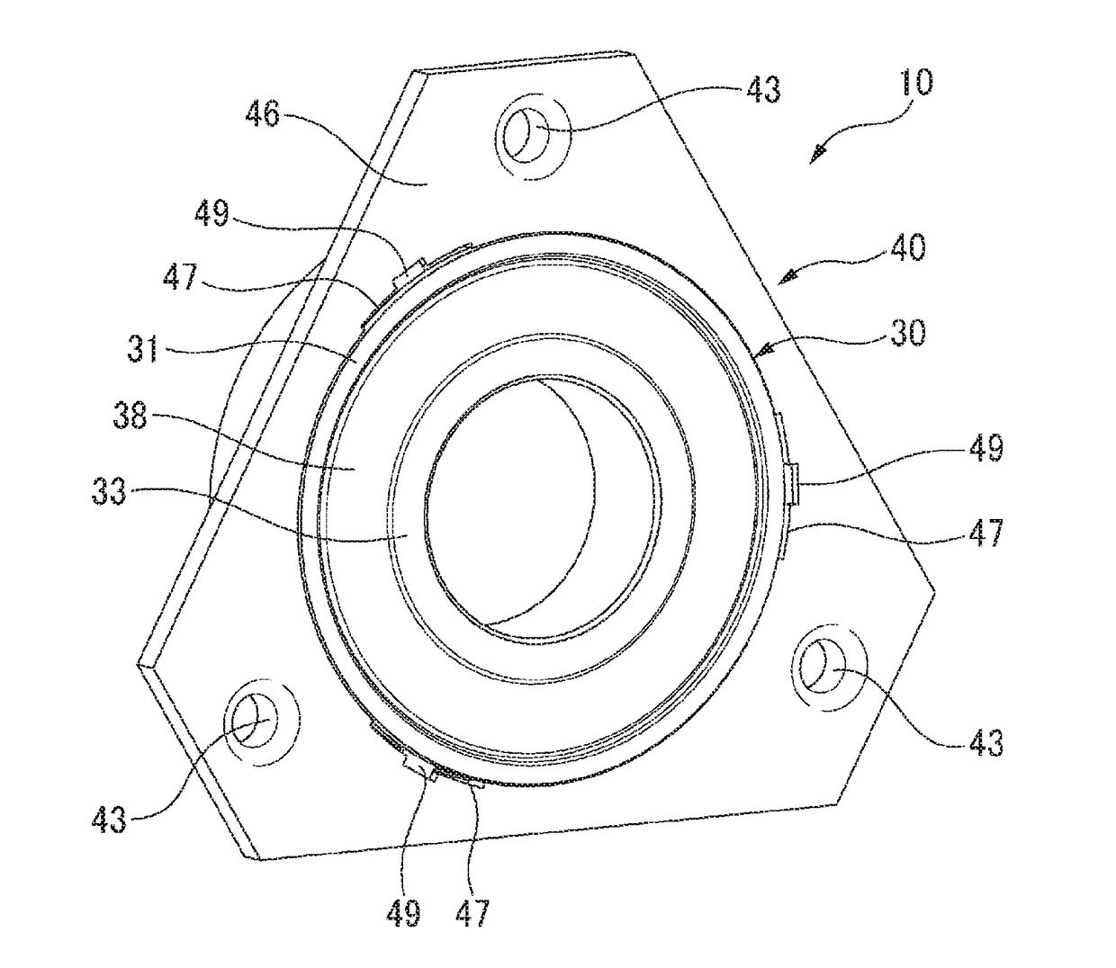
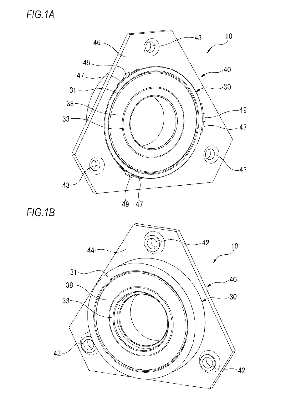
[0065]A bearing device 10 has a radial rolling bearing 30 and a retainer plate 40 configured to fix the radial rolling bearing 30 to a housing 103 (refer to FIG. 22). The radial rolling bearing 30 and the retainer plate 40 are mounted so as not to separate from each other, which will be described later.

[0066]As shown in FIG. 4A, the radial rolling bearing 30 has an outer ring 31 having an outer ring raceway 32 on an inner peripheral surface, an inner ring 33 having an inner ring raceway 34 on an outer peripheral surface, and balls 35, which are a plurality of rolling elements held at a cage 36 and arranged to be freely rollable between the outer ring raceway 32 and the inner ring raceway 34. An outer periphery of one axial end portion of the outer ring 31 is formed with a small-diameter step portion 37 having a step portion outer peripheral surface 37a ...

second embodiment

[0089]Subsequently, a bearing device in accordance with a second embodiment of the present invention is described with reference to FIGS. 9 to 11.

[0090]As shown in FIG. 9, the tapered part 47 of the retainer plate 40 of the second embodiment is formed to have a radial width W greater than the first embodiment. Also, an outer diameter of the tapered part 47 is set to be located at a radially outermore side than an outer diameter of the punch 50 when the retainer plate 40 having the fitting hole 41 to be fitted to the small-diameter step portion 37 is set to the press device. Therefore, the punch 50 crushes only the tapered part 47 to form the engagement claw 49 without contacting (crushing) the backside 46 of the retainer plate 40 (refer to FIG. 11).

[0091]Specifically, as shown in FIGS. 10A to 10D, after fitting the fitting hole 41 of the retainer plate 40 to the small-diameter step portion 37 of the outer ring 31, the punch 50 is arranged to face the tapered part 47 of the fitting h...

third embodiment

[0095]In the below, a bearing device in accordance with a third embodiment of the present invention is described with reference to FIGS. 13A to 14.

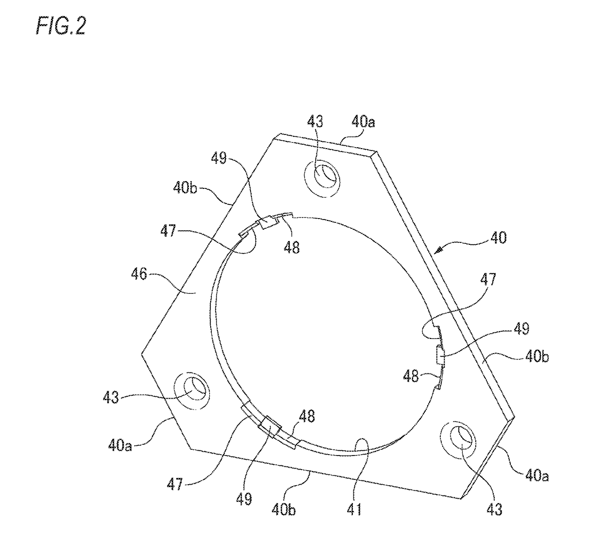
[0096]In the first and second embodiment, the relief part 48 and the tapered part 47 are formed to have the same arc length. However, in the third embodiment, the tapered part 47 has an arc length shorter than an arc length of the relief part 48, and is formed at the peripheral edge between the inner peripheral surface of the relief part 48 and the backside 46 of the retainer plate.

[0097]Thereby, since positions of a circumferential end portion 47a of the tapered part 47 and a circumferential end portion 48a of the relief part 48 are different, it is possible to reduce load that is to be applied to a punch form, particularly to a corner part of a form configured to form the circumferential end portion 48a of the relief part 48.

[0098]The other configurations and operations are the same as the first and second embodiments.

[0099]In the meant...


PUM


Abstract

An outer peripheral surface of the small-diameter step portion is formed with an engagement groove extending in a circumferential direction. The retainer plate has a plurality of engagement claws protruding radially inward from an inner periphery of the retainer plate defining the fitting hole and configured to be engaged to the engagement groove. In a state that the fitting hole is fitted to the small-diameter step portion, the engagement claws are formed by axially pressing the inner periphery of the retainer plate, including at least thickness reduction parts formed in advance at a peripheral edge between an inner peripheral surface of the fitting hole and a side surface of the retainer plate, and plastically deforming the inner periphery of the retainer plate so as to protrude radially inward, and the engagement claws are engaged to the engagement groove.

Description

TECHNICAL FIELD[0001]The present invention relates to a bearing device and a method for manufacturing the bearing device, and more specifically, to a bearing device to be used for a rotation support part of a gear or the like of a transmission or a differential gear device and a method for manufacturing the bearing device.RELATED ART[0002]In the related art, a bearing device configured to support a rotary shaft for which a pulley, a gear and the like of a transmission for an automobile are provided has been known which includes a rolling bearing having a plurality of rolling elements arranged between an inner ring and an outer ring and a retainer plate configured to fix the rolling bearing to a housing with being in contact with an axial end surface of the outer ring of the rolling bearing. Also, in recent years, it is needed to miniaturize the automobile and the transmission. As the bearing device satisfying the need, a bearing device has been known in which a small-diameter step p...

Claims


Application Information

Patent Timeline
IPC IPC(8): F16C19/06F16C35/067F16C43/04F16C33/58
CPCF16C19/06F16C43/04F16C35/067F16C33/58F16C33/586F16C2226/52F16C2226/60F16C2361/61
Inventor ISHIBASHI, YUTAKA
Owner NSK LTD
Why Eureka
Try Eureka