
Eureka
For R&D, Eureka makes reading and utilizing patents & technical documents easy.
Eureka AIR
Designed for self-driven R&D workflows. Generate viable solutions, solve complex R&D challenges, empower your innovation with AI.

Eureka Materials
Designed for material experts only. Revolutionize your material R&D, from search, analyze, to developing new materials.

TechResearch
Generate reliable direction feasibility study reports for your R&D in just a few steps.

TechSeek
Discover and master advanced knowledge NOW. Basics, ideas, possibilities, all at once.

TechMind
As an expert in R&D Theories, TechMind can generates customized viable solutions instantly.

TechRisk
Analyze your overall solution with one click, know your potential R&D risks in advance.

TechMonitor
Get weekly tech updates, stay abreast of the latest tech innovations and key insights.
Rotating Electric Machine or Wind Power Generation System
- Summary
- Abstract
- Description
- Claims
- Application Information
AI Technical Summary
Benefits of technology
Problems solved by technology
Method used
Image

Examples
embodiment 1
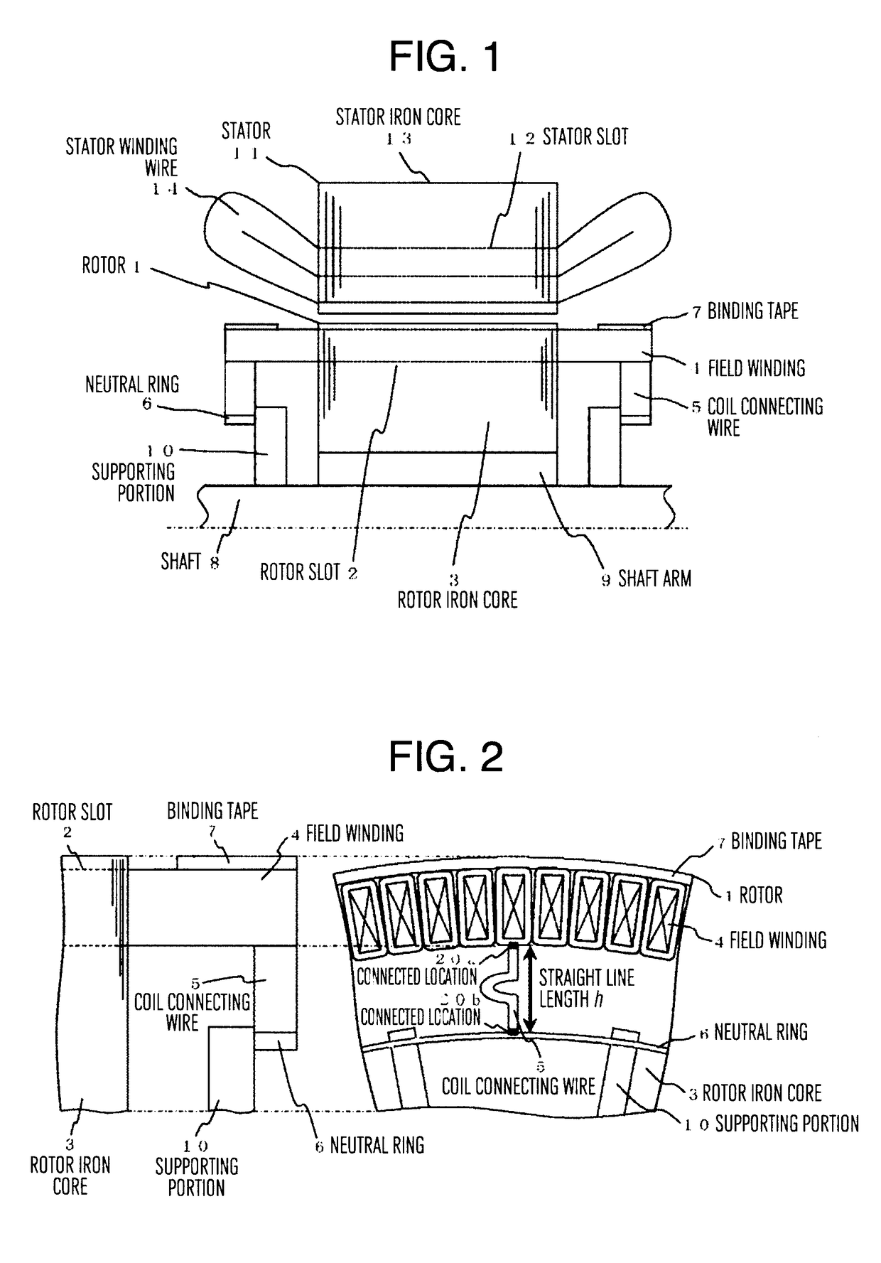
[0024]FIG. 1 is a sectional view in an axial direction of part of an upper half of an alternating-current excitation synchronous rotating electric machine. In FIG. 1, a stator 11 includes, on its inner periphery, a stator slot 12 continuously formed in the axial direction, and includes a stator iron core 13 that is a stack of a plurality of thin steel plates such as electromagnetic steel plates in the axial direction, and a stator winding wire 14 wound around the stator slot 12.
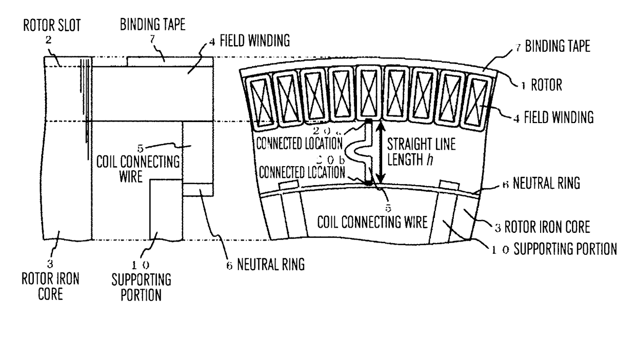
[0025]A rotor 1 concentrically positioned on an inner side of the stator 11 with an air gap interposed therebetween includes, on its outer periphery, a rotor slot 2 continuously formed in the axial direction, includes a rotor iron core 3 that is a stack of a plurality of thin steel plates such as electromagnetic steel plates in the axial direction, and a field winding 4 wound around the rotor slot 2, and includes a shaft 8 having a longitudinal direction aligned with the axial direction and disposed on an inn...
embodiment 2
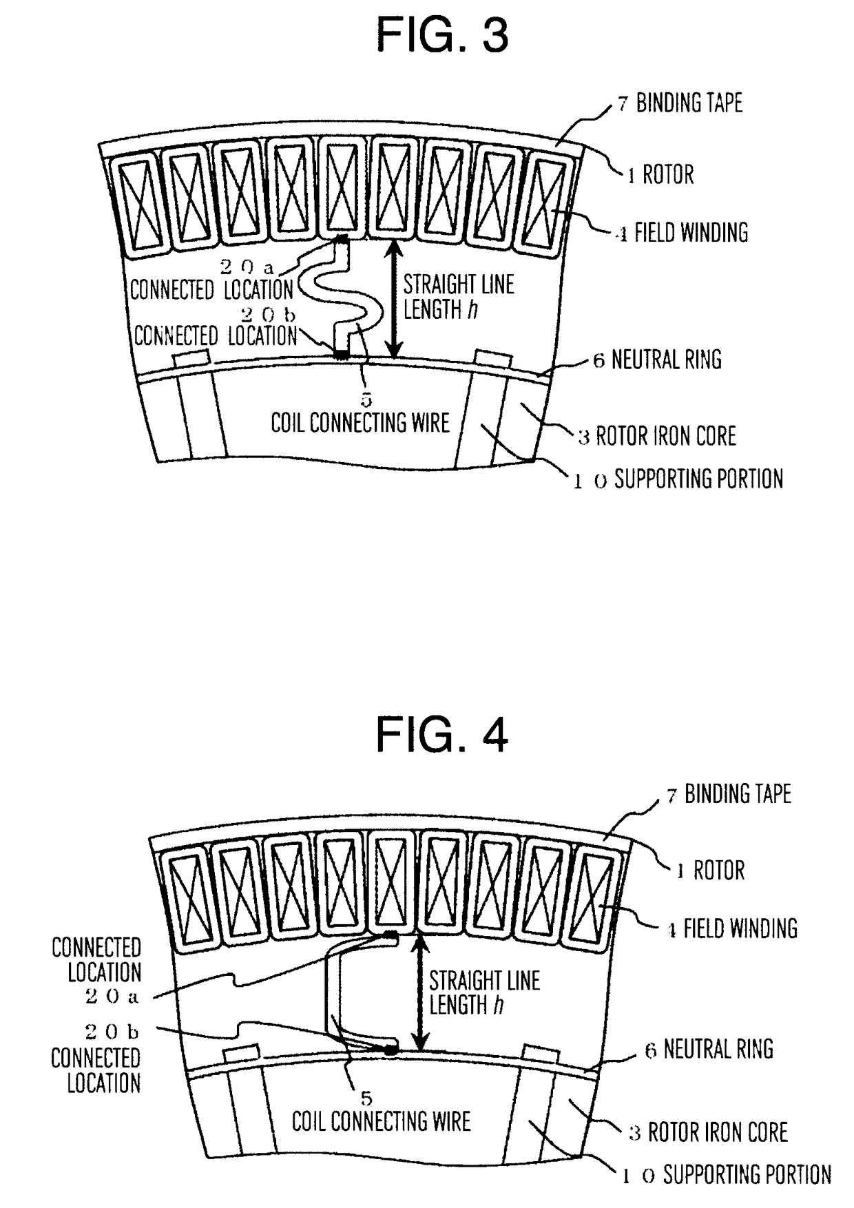
[0040]FIG. 6 illustrates a partially enlarged section view of the peripheral part of the rotor of an alternating-current excitation synchronous rotating electric machine according to an embodiment of the present invention (second embodiment). As an example of the present embodiment, unlike Embodiment 1, as illustrated in FIG. 6, a cantilever is provided by joining an arc-shaped component including a conductor, with the neutral ring 6 at a connected location 20c, and the cantilever of the neutral ring 6 is joined with the coil connecting wire 5 at the connected location 20b. Any duplicate description of the above description will be omitted in the following.
[0041]In the present embodiment, in addition to the effect described in Embodiment 1, part of the amount of displacement of the field winding 4, which cannot be absorbed through the expansion and contraction of the slack part of the coil connecting wire 5, can be absorbed through deflection of the cantilever of the neutral ring 6....
embodiment 3
[0043]FIG. 7 illustrates a partially enlarged section view of the peripheral part of the rotor of an alternating-current excitation synchronous rotating electric machine according to an embodiment of the present invention (third embodiment). The present embodiment is different from Embodiment 2 in that the connected location 20b between the coil connecting wire 5 and the neutral ring 6 is shifted in the circumferential direction with respect to a line extending in the radial direction from the rotation center toward the connected location 20a on the field winding 4 including the coil connecting wire 5. Any duplicate description of the above description will be omitted in the following.
[0044]In the present embodiment, the coil connecting wire 5 can be made in parallel to a joining surface with respect to the neutral ring 6 by shifting the connected location 20b of the coil connecting wire 5 to a position in the circumferential direction. Accordingly, the joining area of the connected...
PUM
 Abstract
Description
Claims
Application Information
 - R&D Engineer
- R&D Manager
- IP Professional
- Industry Leading Data Capabilities
- Powerful AI technology
- Patent DNA Extraction
Browse by: Latest US Patents, China's latest patents, Technical Efficacy Thesaurus, Application Domain, Technology Topic, Popular Technical Reports.
© 2024 PatSnap. All rights reserved.Legal|Privacy policy|Modern Slavery Act Transparency Statement|Sitemap|About US| Contact US: help@patsnap.com